Diffuse irradiance
Because it gathers light from every direction around an object, IBL is in effect a much better version of the ambient term, and even a rough stand-in for global illumination. For PBR that makes a big difference: the metals at the end of the last chapter looked dark and wrong precisely because there was nothing around them to reflect.
Let's look at the reflectance equation again:
\[ L_o(p,\omega_o) = \int\limits_{\Omega} \left( k_d\frac{c}{\pi} + k_s\frac{D\,F\,G}{4(\omega_o \cdot n)(\omega_i \cdot n)} \right) L_i(p,\omega_i)\, (n \cdot \omega_i)\, d\omega_i \]Our job, as before, is to evaluate the integral over all incoming directions \(\omega_i\) in the hemisphere \(\Omega\). With point lights that was easy, because only four directions carried any light. Now every direction can, which leaves us with two problems to solve:
- we need a way to look up the radiance arriving from any direction \(\omega_i\), and
- evaluating the integral has to be fast enough for real time.
The first is the easy one. An environment cubemap is exactly a function from directions to light: sample it with a direction and it returns the radiance arriving from that way. In HLSL it is one line:
float3 radiance = environment.Sample(linear_clamp, wi).rgb;The second is harder. Doing the integral properly means sampling the environment in a great many directions, for every pixel, every frame, which is far too slow. So we will precompute as much of it as we can. To see what can be precomputed, notice that the BRDF is a sum of a diffuse part and a specular part, so the integral splits into two integrals that we can handle one at a time:
\[ L_o(p,\omega_o) = \int\limits_{\Omega} \left(k_d\frac{c}{\pi}\right) L_i(p,\omega_i)\, (n \cdot \omega_i)\, d\omega_i + \int\limits_{\Omega} \left(k_s\frac{D\,F\,G}{4(\omega_o \cdot n)(\omega_i \cdot n)}\right) L_i(p,\omega_i)\, (n \cdot \omega_i)\, d\omega_i \]This chapter is about the first one, the diffuse part. The next is about the second.
In the diffuse integral, the Lambert term \(k_d \frac{c}{\pi}\) doesn't depend on \(\omega_i\) at all. The albedo, the refracted fraction and \(\pi\) are the same for every incoming direction, so we can pull them out in front:
\[ L_o(p,\omega_o) = k_d\frac{c}{\pi} \int\limits_{\Omega} L_i(p,\omega_i)\, (n \cdot \omega_i)\, d\omega_i \]
What's left inside depends only on the environment and on the orientation of the hemisphere, that is, on the normal \(n\). (It also depends on the position \(p\), but we assume, for now, that every point sees the environment as if from its centre.) A function of one direction is something we can store in a cubemap. So for every direction we can compute the integral once, ahead of time, and store the result in a new cubemap texel pointing that way. Computing it means visiting, for each output direction, a large number of directions over the hemisphere around it and averaging what they see. That kind of operation, where every output value is built from many input values around it, is a
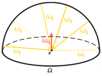
The resulting cubemap stores, for every direction, the total diffuse light that a surface facing that way would receive from the whole environment. It is called an
Here is an environment cubemap beside the irradiance map made from it (images courtesy of Wave Engine, by way of LearnOpenGL):
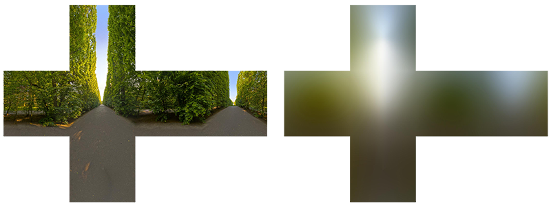
The irradiance map looks like the environment blurred beyond recognition, which is what it is: each texel is an average over half the sphere, so only broad changes in brightness and colour survive. Sampling it with a normal gives that normal's share of the environment's diffuse light.
PBR and HDR
The last chapter showed why PBR needs high dynamic range: lights are given in something like physical units, and the gap between a desk lamp and the sun is enormous. Image based lighting needs it too, and in a more awkward place, because now the light comes from a texture. The cubemaps of the Cubemaps chapter were ordinary 8-bit images, with every value between 0 and 1. That is fine for a background, but as a source of light it is useless: a window and the sun in it would both be stored as 1.0, and the sun would light the scene no more than a white wall. To use an environment as light we need it stored in HDR.
The Radiance HDR file format
The .hdr) is the common way to store such images. It keeps values well above 1, so the sun can be thousands of times brighter than the shadows, but stores them compactly: each pixel is four bytes, three 8-bit mantissas for red, green and blue that share one 8-bit exponent (
Free HDR environments are easy to find (the sIBL Archive and Poly Haven have many). Ours is newport_loft.hdr, a sunny living room. It looks like this:
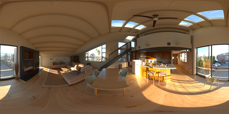
That is not six cube faces but one distorted panorama: the whole sphere of directions unrolled onto a rectangle, longitude across and latitude down, the way a world map unrolls the globe. This is an
Loading an HDR image
LearnOpenGL loads HDR files with stb_image. We don't use stb; our image loader in image.rasm reads ordinary images through Windows' own WIC codecs, which don't handle Radiance files, so it has a small reader of its own for them,
image: struct = {
    pixels: *u8                            ; RGBA8, width * height * 4 bytes (image_load_hdr: 4 floats a pixel)
    width: u32
    height: u32
}
A Radiance file starts with a text header, ended by a blank line, then a line giving the size, such as -Y 800 +X 1600: 800 rows from top to bottom, 1600 pixels across. The pixel rows follow, each one compressed with a simple run-length encoding, one channel at a time. The reader reads the whole file into the arena, expands each row into RGBE bytes, and then turns every pixel into floats:
; mantissa / 256 * 2^(e - 128) = mantissa * 2^(e - 136), and e = 0 means
; black. 2^(e - 136) is built straight from its bits: a float's exponent
; field holds e - 136 + 127.
  mov r8, image_hdr_row
  xor r14, r14
pixels:
  movzx eax, byte ptr [r8 + r14 * 4 + 3]
  sub eax, 9
  jg normal_scale
  xor eax, eax                           ; too small for a normal float: black
  jmp have_scale
normal_scale:
  shl eax, 23
have_scale:
  movd xmm1, eax
  shufps xmm1, xmm1, 0
  pmovzxbd xmm0, dword ptr [r8 + r14 * 4]
  cvtdq2ps xmm0, xmm0
  mulps xmm0, xmm1
  movups xmmword ptr [r15], xmm0
  mov dword ptr [r15 + 12], 0x3F800000   ; a = 1
  add r15, 16
  inc r14
  cmp r14, image_hdr_w
  jb pixels
The reader's working values, the buffer holding one decoded row and the image's width, are globals named after the include (image_hdr_row, image_hdr_w), since rasm has no local variables; the pointer being written, r15, and the counter, r14, are callee-saved registers that
Each mantissa byte is a fraction of 256, and the exponent is stored with an offset of 128, so a channel's value is \(m / 256 \cdot 2^{e - 128}\), or \(m \cdot 2^{e - 136}\). The lessons call no maths library, so there is no
The rest is SSE, a whole pixel at a time. shufps copies the scale into all four lanes of xmm1; pmovzxbd widens the pixel's four bytes into four 32-bit integers, cvtdq2ps turns them into floats, and one mulps scales red, green and blue together. The fourth lane held the exponent byte, so it is overwritten with 1.0 for alpha. A float immediate is written as its bits, 0x3F800000; a literal like 1.0 in rasm is a constant in memory, not an immediate. The rows come out top first, as Direct3D lays out a texture, so unlike LearnOpenGL (which asks stb to flip the image for OpenGL's bottom-up textures) nothing is flipped.
The floats go straight into a texture, in gpu.rasm:
; load_hdr's
load_hdr_image: image = {}
load_hdr_desc: D3D11_TEXTURE2D_DESC = {
    .MipLevels = 1,
    .ArraySize = 1,
    .Format = DXGI_FORMAT.DXGI_FORMAT_R32G32B32A32_FLOAT,
    .SampleDesc = { .Count = 1 },
    .BindFlags = D3D11_BIND_FLAG.D3D11_BIND_SHADER_RESOURCE,
}
load_hdr_init: D3D11_SUBRESOURCE_DATA = {}
load_hdr_texture: *ID3D11Texture2D = {}
load_hdr_srv: *ID3D11ShaderResourceView = {}

; rcx: path of a Radiance .hdr -> rax: its view, as linear float RGBA
load_hdr: proc(path: *const c8) -> *ID3D11ShaderResourceView = {
    push rbx
    sub rsp, 32                            ; 32 shadow; entry 8 + push 8 + 32 lands on 16
    mov rbx, rcx
    invoke(image_load_hdr, load_hdr_image&, rbx)
    ; ...
    mov eax, load_hdr_image.width
    mov load_hdr_desc.Width, eax
    shl eax, 4                             ; 16 bytes a pixel
    mov load_hdr_init.SysMemPitch, eax
    mov eax, load_hdr_image.height
    mov load_hdr_desc.Height, eax
    mov rax, load_hdr_image.pixels
    mov load_hdr_init.pSysMem, rax
    vcall(device, ID3D11DeviceVtbl.CreateTexture2D, load_hdr_desc&, load_hdr_init&, load_hdr_texture&)
    assert_hr()
    vcall(device, ID3D11DeviceVtbl.CreateShaderResourceView, load_hdr_texture, 0, load_hdr_srv&)
    release(load_hdr_texture)
    mov rax, load_hdr_srv
    add rsp, 32
    pop rbx
    ret
}
What would be local variables are globals named after the proc, each declared with its SDK type. The texture description is known up to its size before the program runs, so it is a designated initialiser (enum members written with their enum's name, DXGI_FORMAT.DXGI_FORMAT_R32G32B32A32_FLOAT), and the code stores only the width and the height, naming the fields: rasm works out each one's offset and size, and C checks them against the header. The frame is written out: rbx keeps the path across the calls and is pushed first, and sub rsp, 32 leaves the 32 bytes of shadow space with rsp back on 16. The COM methods are named by the interface's table of function pointers, ID3D11DeviceVtbl.CreateTexture2D. The lesson calls it with the file's full path:
invoke(filesystem_path, "resources/textures/hdr/newport_loft.hdr")
invoke(load_hdr, rax)
mov hdr_texture, rax
DXGI_FORMAT_R32G32B32A32_FLOAT is four 32-bit floats per texel, 16 bytes, which is why the row pitch is the width shifted left by 4, width * 16. Once the view exists the texture object itself can be released: the view holds a reference that keeps it alive. There is a three-channel 32-bit float format too, but whether hardware can filter it is optional, and the alpha costs us nothing worth worrying about for one texture.
From equirectangular to cubemap
We could sample the panorama directly every time we need the environment, but turning a direction into panorama coordinates costs an
The conversion draws a unit cube from the inside, through a camera at its centre, once for each of the six faces of a cubemap, with each face as the render target. The vertex shader passes on the cube's local position, which, seen from the centre, is the direction to look up:
// The unit cube's corners are the directions to look up, drawn through
// one face's view.
struct sky_vertex
{
    float4 position : SV_Position;
    float3 direction : DIRECTION;
};

sky_vertex vs_main(float3 position : POSITION)
{
    sky_vertex o;
    o.direction = position;
    o.position = mul(projection, mul(view, float4(position, 1.0)));
    return o;
}
The pixel shader turns that direction into the point of the panorama that shows it, with a little trigonometry: the angle around the vertical axis gives u, and the angle above or below the horizon gives v.
// a direction to a point on the panorama: longitude across, latitude down
// (D3D's v runs down the image, so the top row is straight up)
float2 equirect_uv(float3 d)
{
    return float2(atan2(d.z, d.x) / (2.0 * PI) + 0.5, 0.5 - asin(d.y) / PI);
}

float4 ps_main(sky_vertex p) : SV_Target
{
    return float4(equirect.SampleLevel(linear_wrap, equirect_uv(normalize(p.direction)), 0).rgb, 1.0);
}
0.5 - ... where LearnOpenGL adds. The direction must be normalized first; the interpolated cube position is not unit length. The wrapping sampler at s0 lets the filter blend across the left and right edges of the panorama, which meet behind us.
Now the target. A cubemap in Direct3D is a 2D texture array of six slices, with a flag that says to treat it as a cube:
; A cubemap of half floats that can be drawn into, face by face and mip by mip.
cube_target: struct = {
    texture: *ID3D11Texture2D              ; an array of six
    srv: *ID3D11ShaderResourceView         ; of it as a cube, every mip
    size: u32                              ; of a face at mip 0, in pixels
    pad: u32
}
; create_cube_target's: everything but the size, the mip count and whether
; the GPU generates the mips
create_cube_target_desc: D3D11_TEXTURE2D_DESC = {
.ArraySize = 6,
.Format = DXGI_FORMAT.DXGI_FORMAT_R16G16B16A16_FLOAT,
.SampleDesc = { .Count = 1 },
.BindFlags = D3D11_BIND_FLAG.D3D11_BIND_RENDER_TARGET | D3D11_BIND_FLAG.D3D11_BIND_SHADER_RESOURCE,
}
create_cube_target_view: D3D11_SHADER_RESOURCE_VIEW_DESC = {
.Format = DXGI_FORMAT.DXGI_FORMAT_R16G16B16A16_FLOAT,
.ViewDimension = D3D_SRV_DIMENSION.D3D_SRV_DIMENSION_TEXTURECUBE,
.TextureCube = { .MipLevels = 0xFFFFFFFF }, ; -1: all of them
}
; rcx: cube_target, edx: face size, r8d: mip levels (0: all of them), r9d: 1
; to let the GPU generate the mips
create_cube_target: proc(out: *cube_target, face_size: u32, mips: u32, generate_mips: b32) = {
push rbx
sub rsp, 32 ; 32 shadow; entry 8 + push 8 + 32 lands on 16
mov rbx, rcx
mov [rbx].cube_target.size, edx
mov create_cube_target_desc.Width, edx
mov create_cube_target_desc.Height, edx
mov create_cube_target_desc.MipLevels, r8d
mov create_cube_target_desc.MiscFlags, D3D11_RESOURCE_MISC_FLAG.D3D11_RESOURCE_MISC_TEXTURECUBE
test r9d, r9d
jz no_generate
mov create_cube_target_desc.MiscFlags, D3D11_RESOURCE_MISC_FLAG.D3D11_RESOURCE_MISC_TEXTURECUBE | D3D11_RESOURCE_MISC_FLAG.D3D11_RESOURCE_MISC_GENERATE_MIPS
no_generate:
lea rax, [rbx].cube_target.texture
vcall(device, ID3D11DeviceVtbl.CreateTexture2D, create_cube_target_desc&, 0, rax)
assert_hr()
lea rax, [rbx].cube_target.srv
vcall(device, ID3D11DeviceVtbl.CreateShaderResourceView, [rbx].cube_target.texture, create_cube_target_view&, rax)
assert_hr()
add rsp, 32
pop rbx
ret
}
Both live in pbr.rasm. The view's description never changes, so it is all initialiser; the texture's is everything but the size, the mip count and the misc flags, which the proc stores from its arguments, read straight from edx, r8d and r9d. [rbx].cube_target.size names a field through a register: the struct is at rbx, and rasm adds the field's offset and takes its size. 0xFFFFFFFF, -1 in the 32-bit MipLevels of the view, is what Direct3D reads as "every level from the first down".
It is both a render target, so we can draw into it, and a shader resource, so we can sample it afterwards. Half floats, DXGI_FORMAT_R16G16B16A16_FLOAT, keep the HDR range at half the cost of 32-bit floats; Direct3D has no three-channel half-float format, so the fourth channel comes along. The shader resource view is a TEXTURECUBE view, which is what lets a shader declare it as a TextureCube and sample it with a direction. The environment cube is 512 by 512 per face, with a full mip chain that the hardware can generate for us; the next chapter needs the mips.
invoke(create_cube_target, env_cubemap&, 512, 0, 1)
invoke(shader_use, equirect_shader&)
invoke(bind_texture, 0, hdr_texture)
invoke(render_to_cube, env_cubemap&, 0, transforms_buffer, cube_vb)
call unbind_textures
vcall(context, ID3D11DeviceContextVtbl.GenerateMips, env_cubemap.srv)
pbr.rasm, does the drawing. It is the piece we will reuse for every precomputation in this chapter and the next, so it is worth reading closely:
; the direction each cube face looks along, and which way is up in it: +x, -x, +y, -y, +z, -z
cube_face_targets: [6]const vec3 = {
    {  1.0,  0.0,  0.0 },
    { -1.0,  0.0,  0.0 },
    {  0.0,  1.0,  0.0 },
    {  0.0, -1.0,  0.0 },
    {  0.0,  0.0,  1.0 },
    {  0.0,  0.0, -1.0 },
}
cube_face_ups: [6]const vec3 = {
    {  0.0, -1.0,  0.0 },
    {  0.0, -1.0,  0.0 },
    {  0.0,  0.0,  1.0 },
    {  0.0,  0.0, -1.0 },
    {  0.0, -1.0,  0.0 },
    {  0.0, -1.0,  0.0 },
}
cube_face_eye: const vec3 = {}
; render_to_cube's. The model matrix is the identity, so it is data; the
; transforms' view_position is never read by these shaders and stays 0.
render_to_cube_t: transforms = {}
render_to_cube_model: const mat4 = { .m = { 1.0, 0.0, 0.0, 0.0, 0.0, 1.0, 0.0, 0.0, 0.0, 0.0, 1.0, 0.0, 0.0, 0.0, 0.0, 1.0 } }
render_to_cube_rtv_desc: D3D11_RENDER_TARGET_VIEW_DESC = {
.Format = DXGI_FORMAT.DXGI_FORMAT_R16G16B16A16_FLOAT,
.ViewDimension = D3D11_RTV_DIMENSION.D3D11_RTV_DIMENSION_TEXTURE2DARRAY,
.Texture2DArray = { .ArraySize = 1 }, ; one face at a time
}
render_to_cube_rtv: *ID3D11RenderTargetView = {}
; rcx: cube_target, edx: mip, r8: transforms constant buffer, r9: the unit
; cube's vertex buffer
;
; Draws the unit cube around the origin once per face, through a 90-degree
; view looking out of that face, with whatever shader is bound: each face's
; pixels see the directions that face covers. A cubemap's faces are laid out
; left-handed, which no right-handed look-at produces; flipping the
; projection's y fixes that, as GL's bottom-up framebuffer does for free
; there.
render_to_cube: proc(target: *cube_target, mip: u32, constants: *ID3D11Buffer, cube_vb: *ID3D11Buffer) = {
push rbx
push rsi
push rdi
push r12
push r13
sub rsp, 48 ; draw_vertices takes 5: 32 + 8; entry 8 + five pushes 40 + 48 lands on 16
mov rbx, rcx ; target
mov edi, edx ; mip
mov r12, r8 ; constants
mov r13, r9 ; cube_vb
; projection = scale(1, -1, 1) * perspective(90 degrees, 1, 0.1, 10)
movss xmm0, 10.0
movss dword ptr [rsp + 32], xmm0 ; z_far
movss xmm0, 90.0
call radians
movaps xmm1, xmm0 ; fovy
movss xmm2, math_one ; aspect
movss xmm3, 0.1 ; z_near
lea rcx, render_to_cube_t.projection
call m4_perspective
; the second row, m[4..7], negated: four floats at once
movups xmm0, xmmword ptr render_to_cube_t.projection.m[4]
xorps xmm0, math_sign_mask
movups xmmword ptr render_to_cube_t.projection.m[4], xmm0
; the face's size at this mip
mov ecx, edi
mov eax, [rbx].cube_target.size
shr eax, cl
invoke(set_viewport, rax, rax)
; Texture2DArray is a member of the view's anonymous union, at offset 8
; after Format and ViewDimension: named straight through it, as in C.
mov render_to_cube_rtv_desc.Texture2DArray.MipSlice, edi
xor esi, esi ; face
faces:
mov render_to_cube_rtv_desc.Texture2DArray.FirstArraySlice, esi
vcall(device, ID3D11DeviceVtbl.CreateRenderTargetView, [rbx].cube_target.texture, render_to_cube_rtv_desc&, render_to_cube_rtv&)
assert_hr()
vcall(context, ID3D11DeviceContextVtbl.OMSetRenderTargets, 1, render_to_cube_rtv&, 0)
imul eax, esi, sizeof(vec3)
lea r8, cube_face_targets
add r8, rax
lea r9, cube_face_ups
add r9, rax
lea rdx, cube_face_eye
lea rcx, render_to_cube_t.view
call m4_look_at
invoke(draw_vertices, r12, render_to_cube_t&, r13, 36, render_to_cube_model&)
release(render_to_cube_rtv)
inc esi
cmp esi, 6
jb faces
add rsp, 48
pop r13
pop r12
pop rdi
pop rsi
pop rbx
ret
}
Its four arguments arrive in rcx, edx, r8 and r9, and since every one of them is needed after the calls, they move at once into callee-saved registers, pushed at the start with rsi (the face counter); the five pushes and sub rsp, 48 leave room for rsp back on 16. The model matrix is the identity, so instead of a call to
For each face it makes a render target view onto exactly one slice of the array, at one mip level, binds it, and draws the cube with a camera looking out through that face. The faces are in Direct3D's order (+x, -x, +y, -y, +z, -z), and a field of view of 90 degrees with an aspect ratio of 1 makes each view cover exactly one face. There is no depth buffer, the 0 in shr eax, cl: a variable shift count has to be in cl), which will matter in the next chapter.
rcx; the field of view, aspect ratio and near plane go in xmm1, xmm2 and xmm3, the registers of their positions; and the fifth, the far plane, goes on the stack, at [rsp + 32], just above the 32 bytes of shadow space. It goes there first, through xmm0, which is free again for xmm0). The float literals, 10.0, 90.0 and 0.1, are constants the assembler keeps in read-only memory, so movss loads them like any other float in memory. Each face's view matrix is picked by multiplying the face number by the size of a vec3 with imul and adding it to the tables' addresses.
The cube_face_targets and cube_face_ups are LearnOpenGL's six capture views, but the projection has an extra scale by (1, -1, 1) that flips y: xorps with math_sign_mask flips the sign of all four floats of the matrix's second row, which is what multiplying by that scale on the left does. m[4] is the fifth float, the start of that row: an index in rasm counts elements, not bytes. The reason is in the comment above the function. The faces of a cubemap are laid out as if seen from inside the cube by a left-handed camera: on the +x face, for example, u runs towards -z and v runs down towards -y. A right-handed look-at camera facing +x with +y up would see +z on its right, a mirror image of what the face expects. The capture views fix the left and right by turning each side camera upside down (up is -y). OpenGL then gets the picture upright again for free, because it stores the rows of a render target bottom first. Direct3D stores them top first, so we turn the image back over ourselves, by negating y after projection. Mirroring one axis also reverses the winding order of every triangle, which is one more reason culling stays off in these lessons.
Finally, the input texture is unbound:
unbind_textures_views: [8]*ID3D11ShaderResourceView = {}    ; always zero

; Clears the pixel shader's texture registers t0..t7. A texture cannot be read
; and drawn into at once, so this runs before drawing into one that was just
; being read.
unbind_textures: proc() = {
    sub rsp, 40                            ; 32 shadow, and rsp back on 16
    vcall(context, ID3D11DeviceContextVtbl.PSSetShaderResources, 0, 8, unbind_textures_views&)
    add rsp, 40
    ret
}
The eight empty views are a global that starts at zero and is never written, so there is nothing to clear before the call. Direct3D will not let a resource be bound for reading and for writing at the same time. The next step reads the cube we just wrote, and the one after draws into another cube; if a view of a texture is still in a shader slot when that texture is bound as a target, the runtime quietly unbinds it (and the debug layer complains). Emptying the slots ourselves keeps every step's bindings explicit.
Showing the environment
To see the result, the program draws the cube map as a skybox around the scene, much as in Cubemaps:
sky_vertex vs_main(float3 position : POSITION)
{
    sky_vertex o;
    o.direction = position;
    // the view without its translation, and z = w: the far plane, as in 4.6.1
    float4x4 rotation = view;
    rotation[0][3] = 0.0;
    rotation[1][3] = 0.0;
    rotation[2][3] = 0.0;
    o.position = mul(projection, mul(rotation, float4(position, 1.0))).xyww;
    return o;
}
The skybox must not move with the camera, so the translation is removed from the view matrix. LearnOpenGL does that with mat4(mat3(view)); we clear the translation directly. Our matrices multiply column vectors (mul(M, v) is \(M v\)), so the translation sits in the fourth column, which with row-major storage is element 3 of each of the first three rows. Writing .xyww makes z equal to w, so after the perspective divide every skybox pixel lands at depth 1.0, the far end of Direct3D's 0 to 1 range. With the depth buffer cleared to 1.0, that only passes a test of "less or equal", so the skybox is drawn last with its own depth state, which also leaves the depth buffer unwritten:
; The sky is drawn last, at the far plane: it passes where nothing else was
; drawn, and leaves the depth buffer alone.
sky_depth_desc: D3D11_DEPTH_STENCIL_DESC = {
    .DepthEnable = 1,
    .DepthWriteMask = D3D11_DEPTH_WRITE_MASK.D3D11_DEPTH_WRITE_MASK_ZERO,
    .DepthFunc = D3D11_COMPARISON_FUNC.D3D11_COMPARISON_LESS_EQUAL,
}
sky_depth: *ID3D11DepthStencilState = {}vcall(device, ID3D11DeviceVtbl.CreateDepthStencilState, sky_depth_desc&, sky_depth&)The description is the lesson's data, complete before the program runs; at startup there is only the call that makes the state object from it. Each frame, after the spheres:
; render skybox (render as last to prevent overdraw)
invoke(shader_use, background_shader&)
invoke(bind_texture, 0, env_cubemap.srv)
vcall(context, ID3D11DeviceContextVtbl.OMSetDepthStencilState, sky_depth, 0)
invoke(m4_identity, model_matrix&)
invoke(draw_vertices, transforms_buffer, t&, cube_vb, 36, model_matrix&)
vcall(context, ID3D11DeviceContextVtbl.OMSetDepthStencilState, 0, 0)
The pixel shader samples the cube with the interpolated direction. The environment is HDR, so it needs tone mapping like everything else we draw; the sRGB back buffer takes care of the gamma, as before:
float4 ps_main(sky_vertex p) : SV_Target
{
    float3 color = env.SampleLevel(linear_clamp, p.direction, 0).rgb;
    return float4(color / (color + 1.0), 1.0);
}
It takes some setup to get here: we read an HDR file, unrolled panorama into cube, and drew the cube around us. In return we have a small, reusable system for drawing into all six faces of a cubemap, and that is exactly what the convolution needs.
Cubemap convolution
Back to the goal. For every direction, we want the diffuse integral of the environment over the hemisphere facing that way:
\[ L_o(p,\omega_o) = k_d\frac{c}{\pi} \int\limits_{\Omega} L_i(p,\omega_i)\, (n \cdot \omega_i)\, d\omega_i \]The environment cubemap gives us \(L_i\) for any \(\omega_i\). Sampling every direction is impossible, as there are infinitely many, but a large finite number of them, spread evenly over the hemisphere, gives a good estimate. That is still far too much work per pixel per frame, so we do it once, for every orientation of the hemisphere, and store the results. Then shading a pixel needs a single lookup, by its normal:
float3 ambient = kd * irradiance_map.Sample(linear_clamp, n).rgb * albedo * ao;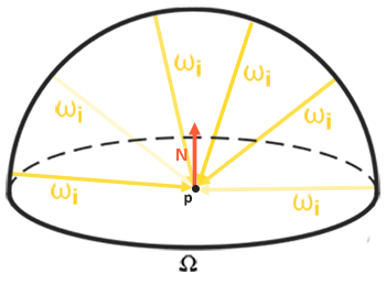
To produce the irradiance map, we take the environment cube, convolve it in a pixel shader, and write the result into another cube. That is exactly what
Integrating over solid angle is awkward, so we change variables to the two angles of spherical coordinates: \(\phi\), the azimuth, going round the hemisphere from 0 to \(2\pi\), and \(\theta\), the angle from the normal, going from 0 at the top to \(\frac{\pi}{2}\) at the rim.
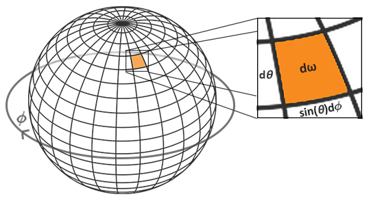
A small step \(d\theta\) by \(d\phi\) covers a patch of the sphere whose size is \(\sin\theta\, d\theta\, d\phi\): the rings of constant \(\theta\) get shorter towards the pole, in proportion to \(\sin\theta\). So \(d\omega_i = \sin\theta\, d\theta\, d\phi\). And \(n \cdot \omega_i\) is \(\cos\theta\) by definition of \(\theta\). The integral becomes:
\[ L_o(p,\phi_o,\theta_o) = k_d\frac{c}{\pi} \int_{\phi = 0}^{2\pi} \int_{\theta = 0}^{\frac{1}{2}\pi} L_i(p,\phi_i,\theta_i) \cos(\theta) \sin(\theta)\, d\theta\, d\phi \]Now we can approximate it with a Riemann sum: step through both angles in small, equal steps, and add up. With \(N_1\) steps in \(\phi\) and \(N_2\) in \(\theta\), each step is \(\Delta\phi = 2\pi / N_1\) by \(\Delta\theta = \frac{\pi}{2} / N_2\), so every term carries a factor \(\Delta\phi\,\Delta\theta = \pi^2 / (N_1 N_2)\). Taking that and the \(\frac{1}{\pi}\) of Lambert together:
\[ L_o(p,\phi_o,\theta_o) \approx k_d\, c\, \frac{\pi}{N_1 N_2} \sum_{\phi} \sum_{\theta} L_i(p,\phi_i,\theta_i) \cos(\theta) \sin(\theta) \]The \(\cos\theta\) is the usual weakening of light that arrives at an angle, and the \(\sin\theta\) compensates for the samples near the top of the hemisphere covering less of it than the samples near the rim. In HLSL:
// Diffuse irradiance: for the normal `n` (this pixel's direction), the
// average of the environment over the hemisphere around it, each direction
// weighted by cos(theta), the way a matte surface receives it.
TextureCube env : register(t0);
SamplerState linear_clamp : register(s1);

static const float PI = 3.14159265359;

float4 ps_main(sky_vertex p) : SV_Target
{
    float3 n = normalize(p.direction);
    // any two directions perpendicular to n and to each other
    float3 up = abs(n.y) < 0.999 ? float3(0.0, 1.0, 0.0) : float3(1.0, 0.0, 0.0);
    float3 right = normalize(cross(up, n));
    up = cross(n, right);

    float3 sum = 0.0;
    float count = 0.0;
    float step = 0.025;
    for (float phi = 0.0; phi < 2.0 * PI; phi += step)
    {
        for (float theta = 0.0; theta < 0.5 * PI; theta += step)
        {
            float3 local = float3(sin(theta) * cos(phi), sin(theta) * sin(phi), cos(theta));
            float3 d = local.x * right + local.y * up + local.z * n;
            // cos(theta) for the angle of incidence, sin(theta) because the
            // rings of the hemisphere shrink towards the pole
            sum += env.SampleLevel(linear_clamp, d, 0).rgb * cos(theta) * sin(theta);
            count += 1.0;
        }
    }
    return float4(PI * sum / count, 1.0);
}
First we need a frame around the normal, two more directions perpendicular to it and to each other, so the hemisphere can be described in local terms and turned to face \(n\). We cross the normal with world up, unless the normal is itself nearly vertical, in which case the cross product would be close to zero and we use the x axis instead. (LearnOpenGL's version always uses world up, which would break down for a normal pointing exactly up or down.)
The two loops step through \(\phi\) and \(\theta\) in steps of 0.025 radians, which is about 250 by 63 directions, roughly sixteen thousand samples per texel. Each pair of angles becomes a direction in local space by the usual spherical-to-Cartesian formula, with z along the normal; multiplying by the frame turns it to world space, and we sample the environment there. The result is PI * sum / count, the sum from the formula above except for \(k_d\) and \(c\). Those depend on the material, which the convolution knows nothing about, so the PBR shader multiplies them in when it looks the map up. Notice that the \(\frac{1}{\pi}\) of Lambert's term is already accounted for here, which is why there is no division by \(\pi\) in the lookup line above.
A smaller step gives a more accurate result at a higher cost. This shader is the slowest thing in the program, and it only runs at startup.
The irradiance map is a cube of 32 by 32 per face, with a single mip level:
; pbr: an irradiance cubemap, by convolving the environment
; ---------------------------------------------------------
invoke(create_cube_target, irradiance_map&, 32, 1, 0)
invoke(shader_use, irradiance_shader&)
invoke(bind_texture, 0, env_cubemap.srv)
invoke(render_to_cube, irradiance_map&, 0, transforms_buffer, cube_vb)
call unbind_textures
32 by 32 is plenty, because the irradiance map has no fine detail: each texel is an average over half the sphere, so neighbouring texels hardly differ, and the bilinear filter fills in between them. Unlike LearnOpenGL, which has to resize its framebuffer's depth attachment for the new size, there is nothing else to change;
If you draw the background from the irradiance map instead of the environment, you should see the room smeared into soft patches of colour: warm and bright towards the windows, darker below. That is the first exercise.
PBR and indirect irradiance lighting
The irradiance map holds the diffuse half of the reflectance integral for light arriving from the environment. It is light that doesn't come from a light source but from the surroundings, which is exactly what the improvised ambient term of the last chapter stood in for. So the 0.03 constant goes, and the irradiance map takes its place. It is bound at t0, with the clamping sampler at s1:
TextureCube irradiance_map : register(t0);
SamplerState linear_clamp : register(s1);
The sampler is created once at startup, for the precomputation passes and the spheres alike, and the map is bound before the grid is drawn:
invoke(create_sampler, D3D11_FILTER.D3D11_FILTER_MIN_MAG_MIP_LINEAR, D3D11_TEXTURE_ADDRESS_MODE.D3D11_TEXTURE_ADDRESS_CLAMP)
mov clamp_sampler, rax
vcall(context, ID3D11DeviceContextVtbl.PSSetSamplers, 1, 1, clamp_sampler&)invoke(shader_use, pbr_shader&)
invoke(bind_constants, 1, material_buffer)
invoke(bind_constants, 2, lights_buffer)
invoke(bind_texture, 0, irradiance_map.srv)Looking it up by the normal gives the irradiance at the pixel. But light from the environment is subject to the same split between reflection and refraction as light from a lamp: some of it reflects off the surface (the specular half, which the next chapter adds) and only the rest is available as diffuse. So, as with direct light, we work out \(k_s\) with Fresnel and take \(k_d\) as what is left, scaled down for metals. With direct light, Fresnel used the halfway vector between the light and the eye. Environment light comes from the whole hemisphere at once, so there is no single halfway vector; instead we use the angle between the normal and the view direction, the nearest thing to a single angle that describes how we look at the surface.
That leaves one problem. The halfway-vector Fresnel of a rough surface is spread over many microfacet orientations, so a rough surface doesn't get much brighter at grazing angles. Using \(n \cdot v\) loses that, and gives every surface the strong rim of a smooth one. On rough dielectrics it shows as a too-bright edge (LearnOpenGL's picture exaggerates it to make the point):

Sébastien Lagarde suggested a fix: let the grazing-angle limit of Fresnel depend on roughness, so rough surfaces rise towards \(1 - roughness\) instead of towards 1:
// For image based light, where there is no single halfway vector: rough
// surfaces get less of the grazing-angle boost.
float3 fresnel_schlick_roughness(float cos_theta, float3 f0, float roughness)
{
    return f0 + (max((1.0 - roughness).xxx, f0) - f0) * pow(saturate(1.0 - cos_theta), 5.0);
}
The
// ambient lighting from the environment: only the diffuse part so far;
// the specular share (Fresnel) is what the surface does not scatter
float3 f0 = lerp(0.04.xxx, albedo, metallic);
float3 ks = fresnel_schlick_roughness(max(dot(n, v), 0.0), f0, roughness);
float3 kd = (1.0 - ks) * (1.0 - metallic);
float3 ambient = kd * irradiance_map.Sample(linear_clamp, n).rgb * albedo * ao;

float3 color = ambient + lo;
return float4(color / (color + 1.0), 1.0);
The image based part of the shader is a single texture lookup; all the hard work was in building the map. The four point lights of the previous chapter are still there, in lo, and the ambient occlusion now darkens real ambient light.
The scene is the grid of spheres from Lighting, metallic increasing upwards and roughness to the right, now standing in the living room:
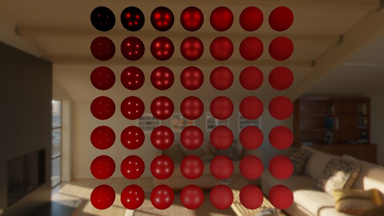
The dielectric spheres in the lower rows now receive the room's light, and are clearly brighter than under the four lamps alone. The metals in the top rows are still almost black apart from their highlights, which is to be expected: a metal has no diffuse light, and diffuse is all we have added. They need reflections, which are the subject of the next chapter. Even so, the spheres already look much more as though they are in the room rather than pasted in front of it.
The full program is here. Its shaders are equirectangular_to_cubemap.hlsl, irradiance_convolution.hlsl, background.hlsl and pbr.hlsl. LearnOpenGL splits this into two programs, one that only converts and shows the environment and one that adds the convolution; ours is both in one.
Additional resources
- Physically based rendering, Coding Labs: the rendering equation and why, and how, to build an irradiance map.
- The Mathematics of Shading, Scratchapixel: spherical coordinates, solid angles and integrals over the sphere, explained slowly.
- RGBE file format: Bruce Walter's notes and reference code for reading and writing Radiance files.
- Introduction to textures in Direct3D 11: texture arrays, cube textures and their mip levels, and how views select parts of them.
- LearnOpenGL's Diffuse irradiance: the OpenGL original of this chapter.
Exercises
- Bind irradiance_map instead of env_cubemap for the skybox, so the background shows the irradiance map. Does it look like a blurred version of the room, brighter where the windows are?
- Change the step of the convolution to 0.1, then to 0.01, and compare the startup time and the result on the spheres. How large can the step get before you can see a difference?
- Replace
fresnel_schlick_roughness in the ambient term with plainfresnel_schlick , and look at the edges of the rough dielectric spheres in the bottom right of the grid. - Skip the cubemap: sample the equirectangular texture directly in
background.hlsl, usingequirect_uv . (You will need to bind the HDR texture in place of the cube; the wrapping sampler is still bound ats0.) Then look straight up and straight down: what happens at the poles?