Hello Triangle
Everything Direct3D draws starts out as points in 3D space, and everything it shows ends up as a grid of coloured pixels in a window. Turning one into the other is the job of the
Each stage does one narrow job, and does it for a great many vertices or pixels at once, which is why GPUs carry thousands of small cores. A few stages run programs we write ourselves. Those programs are
Here are Direct3D 11's stages in order. The ones in green run our shaders; the grey ones are fixed hardware we configure with state objects.
- The
input assembler reads our vertex data out of buffers and groups it intoprimitives : points, lines or triangles, as we ask. - The
vertex shader runs once per vertex. Its main duty is to say where that vertex lands, as a position inclip space . - Tessellation and the
geometry shader can add or reshape primitives. They are optional, and we leave them empty until the geometry shader chapter. - The
rasterizer clips primitives to the visible region and works out which pixels each one covers. - The
pixel shader runs once for every covered pixel and returns its colour. OpenGL calls this stage the fragment shader; it is where most of the interesting work in later chapters happens. - The
output merger does the depth and stencil tests and blending, then writes the result into the render target.
OpenGL ships default shaders for nothing in modern profiles, and neither does Direct3D: a vertex shader and a pixel shader are the minimum before anything is drawn. Let's write both.
Vertex input
The vertex shader has to say where each vertex lands, and it says it in
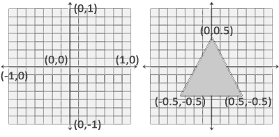
This picture is LearnOpenGL's and holds for Direct3D too, except in depth: Direct3D's z runs from 0 (near) to 1 (far), where OpenGL's runs from -1 to 1. That only starts to matter once we build a projection matrix in Coordinate Systems. The rasterizer then maps NDC to pixels with the
Three corners of a triangle, z left at 0, written as one flat array of floats:
; Positions straight in clip space: x and y from -1 to 1, the centre is 0.
; Counter-clockwise, which these lessons treat as the front.
triangle_vertices: [9]const f32 = {
    -0.9, -0.5, 0.0,
    -0.1, -0.5, 0.0,
    -0.5,  0.5, 0.0,
}
A global in rasm is declared as rin declares one: its name, a colon, its type, and its initial value. [9]const f32 is an array of nine 32-bit floats that nothing may write, so it goes into the read-only data section, and its size is the type's business: sizeof(triangle_vertices) is 36, worked out when the program is built.
This array lives in our program's memory. The GPU wants it in its own, so we copy it into a
buffer_desc: D3D11_BUFFER_DESC = { .Usage = D3D11_USAGE.D3D11_USAGE_IMMUTABLE }    ; create_buffer's
buffer_init: D3D11_SUBRESOURCE_DATA = {}
new_buffer: *ID3D11Buffer = {}
; ...
; ecx: bind flags, rdx: data, r8d: size -> rax: the buffer
;
; An immutable buffer: filled once at creation, never written by the CPU again.
create_buffer: proc(bind: u32, data: *const void, size: u32) -> *ID3D11Buffer = {
    sub rsp, 40
    mov buffer_desc.ByteWidth, r8d
    mov buffer_desc.BindFlags, ecx
    mov buffer_init.pSysMem, rdx
    vcall(device, ID3D11DeviceVtbl.CreateBuffer, buffer_desc&, buffer_init&, new_buffer&)
    mov rax, new_buffer
    add rsp, 40
    ret
}
This is the pattern for nearly every Direct3D object: fill a _DESC struct, call a
- BindFlags says what the buffer will be used for. D3D11_BIND_VERTEX_BUFFER here; the same function makes index buffers and, later, constant buffers.
- Usage says how often the data changes. It plays the part of OpenGL's GL_STATIC_DRAW and friends, but it is a promise the driver holds us to rather than a hint. D3D11_USAGE_IMMUTABLE means the data is given at creation and never written again, so the driver can put it wherever the GPU reads it fastest. Advanced Data uses D3D11_USAGE_DYNAMIC for a buffer rewritten every frame.
invoke(create_buffer, D3D11_BIND_FLAG.D3D11_BIND_VERTEX_BUFFER, triangle_vertices&, sizeof(triangle_vertices))
mov triangle_vb, rax
There is a lot of rasm in those few lines, and it is the same in every chapter from here on, so let's take it apart.
The data is typed. buffer_desc is a D3D11_BUFFER_DESC, the structure from the Windows SDK'sd3d11.h, and it is initialised where it is declared, with adesignated initialiser as in C: Usage is set, and every field not named is zero, which for Direct3D's descriptions is almost always the default we want. Socreate_buffer stores only what changes from call to call. The structure, its fields and their offsets come from the binding inincludes/d3d11.rin, generated from the SDK's headers (see Creating a window).Operands name their fields. mov buffer_desc.ByteWidth, r8dwrites four bytes at the field's offset; rasm works out both the offset and the size from the type, so there is nodword ptrand no number to get wrong, and the C compiler checks the offset against the header on every build. A size that does not match is an error:mov buffer_desc.ByteWidth, r8would be refused, since the field is 32 bits.Enum members are qualified by their enum,D3D11_USAGE.D3D11_USAGE_IMMUTABLEandD3D11_BIND_FLAG.D3D11_BIND_VERTEX_BUFFER, in code as in data.There are no locals. What a procedure needs to keep, or to hand to a COM method by address, is a global: buffer_desc, buffer_init and new_buffer belong tocreate_buffer , which the comment says. The debugger shows each of them by name, with its type and fields. The price is thatcreate_buffer cannot be running twice at once, which nothing here needs.Addresses are writtenname&:buffer_desc&is the address of buffer_desc, where C would write&buffer_desc.The parameter list documents. proc(bind: u32, data: *const void, size: u32)is what the comment above it says in registers: Win64 passes the first four arguments inrcx,rdx,r8andr9, so the flags arrive inecx, the data inrdxand the size inr8d. The names are not operands; the code uses the registers.
Frames, invoke and vcall
The first line of sub rsp, 40, is its add rsp, 40 before the ret takes it down again. Nothing writes this for us: rasm adds no instruction of its own, so every procedure that makes a call sets up its own stack. Win64 asks two things of a caller. It reserves 32 bytes of rsp on a multiple of 16. At entry, rsp is 8 off (the call that got us here pushed the return address), so 40 is 32 for the shadow space and 8 to land on 16. A procedure with more to do pushes the registers it must preserve and reserves room for its calls' extra arguments; the comment on the sub always says how the number was arrived at.
The calls themselves are two macros from includes/calls.rasm, plain text substitution with one definition per argument count.
invoke: macro(f, a1, a2, a3) = {
    mov rcx, a1
    mov rdx, a2
    mov r8, a3
    call f
}
and nothing more, so invoke(create_buffer, ...) above is three movs and a call. rcx as the hidden first argument, this, the method's own arguments follow in rdx, r8 and r9, and the call goes through the object's table of functions:
vcall: macro(obj, method, a1, a2, a3) = {
    mov rcx, obj
    mov rdx, a1
    mov r8, a2
    mov r9, a3
    mov r10, [rcx]
    call [r10].method
}
The method is named by the structure the binding has for the interface's table, so ID3D11DeviceVtbl.CreateBuffer is a field offset like any other, and call [r10].method calls through the slot at that offset. Read vcall(device, ID3D11DeviceVtbl.CreateBuffer, ...) as device->CreateBuffer(...). A call with more arguments than registers stores the rest on the stack first, above the shadow space, which is what the next procedure needs.
Vertex shader
The smallest useful vertex shader takes the position and hands it on. Ours lives in hello_triangle.hlsl, next to the program:
float4 vs_main(float3 position : POSITION) : SV_Position
{
    return float4(position, 1.0);
}
An HLSL shader is an ordinary function, and we choose its name; vs_main is our convention for the vertex shader's entry point. The interesting parts are after the colons. These are
POSITIONis our own name for the input. Any name works; it only has to match the name we give the attribute when we describe the vertex layout below. It is how HLSL gets its inputs where GLSL writeslayout (location = 0) in vec3 aPos.SV_Positionis asystem value : a name the pipeline itself understands. Returning afloat4markedSV_Positionis what GLSL does by assigning gl_Position.
The fourth component, w, is set to 1. Why it exists, and what dividing by it does, comes with perspective in Coordinate Systems.
Compiling a shader
OpenGL compiles GLSL inside the driver while the program runs. Direct3D splits the job in two: a compiler that turns HLSL into bytecode, and the device, which turns bytecode into a shader object. The compiler is d3dcompiler.dll. It can also run ahead of time, as fxc does, but compiling at startup keeps each lesson to its source files and lets us edit a shader without a separate build step.
shader_code: *ID3DBlob = {}            ; compile_shader's results
shader_errors: *ID3DBlob = {}
; ...
; rcx: path, rdx: source, r8: size, r9: entry point, [rsp + 40]: target -> rax: the compiled code
compile_shader: proc(path: *const u8, source: *u8, size: u64, entry: *const u8, target: *const u8) -> *ID3DBlob = {
    sub rsp, 88                        ; D3DCompile takes 11: 32 shadow + 7 * 8, and rsp lands on 16
    mov shader_code, 0
    mov shader_errors, 0
    ; D3DCompile wants (source, size, path): rcx is moved to r8 after rdx has
    ; been moved into rcx, so rcx is kept in r10 first.
    ; invoke(D3DCompile, rdx, r8, rcx, ...) would pass the source as the path.
    mov r10, rcx
    invoke(D3DCompile, rdx, r8, r10, 0, D3D_COMPILE_STANDARD_FILE_INCLUDE, r9, qword ptr [rsp + 128], 0, 0, shader_code&, shader_errors&)
    test eax, eax
    jns compiled
        vcall(shader_errors, ID3D10BlobVtbl.GetBufferPointer)
        invoke(print, "ERROR::SHADER::COMPILATION_FAILED\n%s\n", rax)
        invoke(ExitProcess, 1)
    compiled:
    mov rax, shader_code
    add rsp, 88
    ret
}
We pass the source text, the file name (used only in error messages), the entry point and a vs_5_0 for a vertex shader at Direct3D 11's level. The result comes back in an ID3DBlob, a plain buffer of bytes. On failure the errors blob holds the compiler's messages, with file and line, which we print before giving up.
eax: negative means failure, so test eax, eax sets the sign flag and jns jumps past the error when it is clear. That is all C's FAILED() macro does. Eleven arguments are more than the four registers hold, and this procedure shows each consequence on the page. The frame is bigger: 32 bytes of shadow space and 7 × 8 for the arguments past the fourth, 88 in all, which with the 8 of the return address lands on 16. The eleven-argument r11 into [rsp + 32], [rsp + 40] and so on, then fills rcx, rdx, r8 and r9 in that order; the path arrives in rcx and must end up in r8, but rcx is overwritten with the source before r8 is written, so the path is moved aside into r10 first. And our own fifth argument, the target, was stored by our caller at [rsp + 40], just above the shadow space; after our sub rsp, 88 it is at [rsp + 128], and is passed on from there. The string literal handed to Pixel shader
The pixel shader decides the colour of each pixel the triangle covers. Colours are four floats, red, green, blue and alpha, each from 0 to 1. Ours returns one orange for everything:
float4 ps_main() : SV_Target
{
    return float4(1.0, 0.5, 0.2, 1.0);
}
SV_Target is the system value for "the colour written to render target 0". GLSL declares an out vec4 for this; HLSL marks the return value. Both entry points sit in the same file, so we read it once and compile it twice with different entry points and targets:
invoke(filesystem_path, "src/1.getting_started/2.1.hello_triangle/hello_triangle.hlsl")
mov shader_path, rax
invoke(filesystem_read, rax, shader_size&)
mov shader_source, rax
invoke(compile_shader, shader_path, shader_source, shader_size, "vs_main", "vs_5_0")
mov vs_code, rax
invoke(compile_shader, shader_path, shader_source, shader_size, "ps_main", "ps_5_0")
mov ps_code, rax
push rbx, push rsi and sub rsp, 104: 32 bytes of shadow space and 8 × 8 for the stack arguments, plus 8 so that the return address, the two pushes and the 104 add up to a multiple of 16.
Shader objects
OpenGL links its shaders into one program object, and checks there that the outputs of one stage match the inputs of the next. Direct3D has no program object. Each stage is its own object, created from its bytecode, and bound to its own slot in the pipeline:
vcall(vs_code, ID3D10BlobVtbl.GetBufferPointer)
mov rbx, rax
vcall(vs_code, ID3D10BlobVtbl.GetBufferSize)
mov rsi, rax
vcall(device, ID3D11DeviceVtbl.CreateVertexShader, rbx, rsi, 0, vertex_shader&)
The bytecode's address and size are kept in rbx and rsi, two of the registers a call must leave as it found them (which is why ps_code:
vcall(ps_code, ID3D10BlobVtbl.GetBufferPointer)
mov rbx, rax
vcall(ps_code, ID3D10BlobVtbl.GetBufferSize)
; rax goes straight in: calls.rasm sends the fifth argument through r11,
; so rax, which holds every return value, is safe to pass anywhere.
vcall(device, ID3D11DeviceVtbl.CreatePixelShader, rbx, rax, 0, pixel_shader&)
Mixing and matching is free: any vertex shader can be bound with any pixel shader, so long as what one outputs is what the other reads. Here the pixel shader reads nothing at all, so there is nothing to match yet.
Describing the vertices
The buffer is only bytes. The vertex shader wants a float3 called POSITION. Something has to say how one becomes the other: where each attribute starts in a vertex, what type it is, and which shader input it feeds. OpenGL says it with
; One attribute: three floats, read as POSITION by the vertex shader.
vertex_layout: [1]const D3D11_INPUT_ELEMENT_DESC = {
    { .SemanticName = "POSITION", .Format = DXGI_FORMAT.DXGI_FORMAT_R32G32B32_FLOAT },
}
Each element names the semantic it feeds and the format of the data: DXGI_FORMAT_R32G32B32_FLOAT is three 32-bit floats. The array has one element, initialised with the two fields that matter; the string becomes the address of the text, as it would in C. Every field left out is zero, and zero is what we want for all of them: semantic index 0, vertex buffer slot 0, starting at byte 0 of the vertex, and per-vertex rather than per-instance data (that last one returns in Instancing).
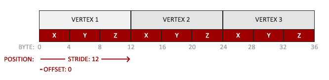
As in LearnOpenGL's picture, the positions are tightly packed: each vertex is 12 bytes, and the position is at offset 0. Where OpenGL puts the stride into the attribute pointer, Direct3D gives it when the buffer is bound, as we will see in the render loop.
The layout is created against the vertex shader's bytecode:
; The layout is created against the compiled vertex shader, which is the
; one place D3D checks that the two agree.
vcall(device, ID3D11DeviceVtbl.CreateInputLayout, vertex_layout&, 1, rbx, rsi, input_layout&)
That is the step OpenGL's linker did for us. Misspell POSITION on either side and creation fails here, at startup, rather than drawing garbage. The layout does not mention any buffer; it only describes vertices. Which buffer they come from is decided when drawing, so one layout serves every mesh with the same vertex format.
The triangle we've all been waiting for
Everything is created. What remains is, every frame, to tell the pipeline what to use and to ask it to draw. A Direct3D
vcall(context, ID3D11DeviceContextVtbl.IASetInputLayout, input_layout)
vcall(context, ID3D11DeviceContextVtbl.IASetPrimitiveTopology, D3D11_PRIMITIVE_TOPOLOGY.D3D11_PRIMITIVE_TOPOLOGY_TRIANGLELIST)
vcall(context, ID3D11DeviceContextVtbl.VSSetShader, vertex_shader, 0, 0)
vcall(context, ID3D11DeviceContextVtbl.PSSetShader, pixel_shader, 0, 0)

vcall(context, ID3D11DeviceContextVtbl.IASetVertexBuffers, 0, 1, triangle_vb&, stride&, offset&)
vcall(context, ID3D11DeviceContextVtbl.Draw, 3, 0)
The prefixes give the stage each call configures: IA the input assembler, VS the vertex shader, PS the pixel shader, and further on RS for the rasterizer and OM for the output merger. The
stride: u32 = 12
; `offset` is a reserved word in MASM (masm64-dx11 had to call
; this `offset_`) and an operator in clang's Intel syntax too. rasm quotes
; every symbol it emits, `[rip + "offset"]`, so the name is free.
offset: u32 = 0
A stride of 12 bytes and an offset of 0. Then
This sits in the render loop from Hello Window, between clearing the back buffer and presenting it. And there it is:

The rectangle to its right is the next section's.
Index buffers
A rectangle is two triangles. Listed as triangles that is six vertices, two of them stored twice, because the triangles share a diagonal. On a rectangle that is a small waste; on a model where every vertex is shared by about six triangles, it is most of the data. The fix is to store each vertex once, and draw from a second list that says which vertices make each triangle. Those are
rectangle_vertices: [12]const f32 = {
    0.1, -0.5, 0.0,   ; bottom left
    0.9, -0.5, 0.0,   ; bottom right
    0.9,  0.5, 0.0,   ; top right
    0.1,  0.5, 0.0,   ; top left
}
rectangle_indices: [6]const u32 = { 0, 1, 2, 0, 2, 3 }
Four vertices, six indices: triangle 0-1-2 is the bottom right half, 0-2-3 the top left. The index buffer is made by the same function with a different bind flag, and drawing swaps
invoke(create_buffer, D3D11_BIND_FLAG.D3D11_BIND_INDEX_BUFFER, rectangle_indices&, sizeof(rectangle_indices))
mov rectangle_ib, raxvcall(context, ID3D11DeviceContextVtbl.IASetVertexBuffers, 0, 1, rectangle_vb&, stride&, offset&)
vcall(context, ID3D11DeviceContextVtbl.IASetIndexBuffer, rectangle_ib, DXGI_FORMAT.DXGI_FORMAT_R32_UINT, 0)
vcall(context, ID3D11DeviceContextVtbl.DrawIndexed, 6, 0, 0)
DXGI_FORMAT_R32_UINT says each index is a 32-bit unsigned integer, matching the u32 array; 16-bit indices would use DXGI_FORMAT_R16_UINT and take half the space.
The input layout is reused unchanged, since the rectangle's vertices have the same format as the triangle's. In OpenGL each shape would get its own VAO, recording its buffers alongside its layout. In Direct3D the layout and the buffers are bound separately, so switching shapes is just binding the other buffers.
Wireframe mode
To see the two triangles, draw only their edges. OpenGL has
; GL's conventions rather than D3D's: counter-clockwise triangles face the
; viewer, and nothing is culled. The wireframe state differs only in the fill,
; so it is a second initialised struct rather than a copy and a store.
raster_desc: D3D11_RASTERIZER_DESC = {
    .FillMode = D3D11_FILL_MODE.D3D11_FILL_SOLID,
    .CullMode = D3D11_CULL_MODE.D3D11_CULL_NONE,
    .FrontCounterClockwise = 1,
    .DepthClipEnable = 1,
}
wire_desc: D3D11_RASTERIZER_DESC = {
    .FillMode = D3D11_FILL_MODE.D3D11_FILL_WIREFRAME,
    .CullMode = D3D11_CULL_MODE.D3D11_CULL_NONE,
    .FrontCounterClockwise = 1,
    .DepthClipEnable = 1,
}
and creates both at startup:
vcall(device, ID3D11DeviceVtbl.CreateRasterizerState, raster_desc&, raster_state&)
vcall(device, ID3D11DeviceVtbl.CreateRasterizerState, wire_desc&, wire_state&)
Tab flips wireframe (the window procedure records each key press, and eax), and the flag chooses which state to bind each frame:
invoke(key_pressed, VK_TAB)
xor wireframe, eax
; ...
mov rax, raster_state
cmp wireframe, 0
je solid
    mov rax, wire_state
solid:
vcall(context, ID3D11DeviceContextVtbl.RSSetState, rax)
The diagonal across the rectangle is where its two triangles meet. Making state objects once and only binding them in the loop is the Direct3D way throughout: the expensive checking happens at creation, and switching between states is cheap.
Stepping through it
This is a good program to watch run. Build it with python build.py hello_triangle, open it in Visual Studio with devenv /debugexe build\hello_triangle.exe, open hello_triangle.rasm and put a breakpoint on the mov buffer_desc.ByteWidth, r8d line of r8 holding 36. Add buffer_desc to the Watch window: it shows up as a D3D11_BUFFER_DESC, with Usage already 1, D3D11_USAGE_IMMUTABLE. F10 steps one line at a time and fills in ByteWidth, then BindFlags; the whole vcall is one step, and afterwards new_buffer holds the buffer's address. Shift+F11 goes back up to mov triangle_vb, rax after the invoke.
If you got here with both shapes on screen, you have done the hardest part of graphics programming: the first triangle. Everything from here on adds to this, one piece at a time. The full program is here, and its shaders here.
Additional resources
- Graphics pipeline: Microsoft's overview of every Direct3D 11 stage.
- Getting started with the input-assembler stage: buffers, input layouts and topologies in more depth.
- x64 stack usage: the shadow space, stack arguments and alignment that every frame here is built from.
- LearnOpenGL's Hello Triangle: the OpenGL version of this chapter, with its VBOs, VAOs and EBOs.
Exercises
- Draw two triangles side by side with a single
Draw call, by adding three more vertices to the array. Its type,[9]const f32, has to grow with it. - Draw the same two triangles from two separate vertex buffers, binding each in turn.
- Add a second pixel shader entry point,
ps_yellow, to the same.hlslfile, and draw one of the triangles with it. Only one morecompile_shader and one moreCreatePixelShader are needed, and one more global to hold the shader.