Textures
In the last chapter we coloured a triangle by giving each vertex a colour and letting the rasterizer blend them. That only goes so far. To draw something with real detail, a wooden crate or a brick wall, we would need a vertex wherever the colour changes, which means a huge number of vertices, each carrying its own colour.
The usual answer is a
To put an image on a shape, each vertex has to say which point of the image it corresponds to. That point is the vertex's
Texture coordinates
Texture coordinates run from 0 to 1 along each axis of the image, whatever its size in pixels. They are usually called \(u\) (across) and \(v\) (down), and in Direct3D they start at the image's top-left corner: \((0, 0)\) is the top-left, \((1, 0)\) the top-right, \((0, 1)\) the bottom-left and \((1, 1)\) the bottom-right.
This is the opposite of OpenGL, where \((0, 0)\) is the bottom-left of a texture, and it is the one convention in this chapter that differs. Image files store their top row first; Direct3D puts the first row it is given at \(v = 0\), and so the two agree, and an image loaded straight from a file is the right way up. OpenGL puts the first row at the bottom, which is why LearnOpenGL has to flip images while loading them. We don't, ever.
This lesson textures the rectangle from Hello Triangle. Each vertex now has a position followed by its texture coordinate, five floats in all:
; x, y, z, then u, v. D3D's texture coordinate (0, 0) is the image's top-left, where GL's is its
; bottom-left, so nothing is flipped on load.
align 4
rectangle_vertices real4 -0.5, -0.5, 0.0,   0.0, 1.0
                   real4  0.5, -0.5, 0.0,   1.0, 1.0
                   real4  0.5,  0.5, 0.0,   1.0, 0.0
                   real4 -0.5,  0.5, 0.0,   0.0, 0.0
rectangle_vertices_size equ $ - rectangle_vertices
The top corners of the rectangle (positive \(y\)) take \(v = 0\), the top of the image, and the bottom corners take \(v = 1\). The four corners of the image land on the four corners of the rectangle, and everything between is filled in by interpolation.
That describes which point of the image each pixel wants. How the image is read there is a separate question, and it has several possible answers. In Direct3D they are collected into a separate object, the
Texture wrapping
Nothing stops a texture coordinate from going below 0 or above 1. What the sampler does then is its
- D3D11_TEXTURE_ADDRESS_WRAP (GL_REPEAT): only the fractional part of the coordinate counts, so the image repeats. 1.25 reads the same as 0.25.
- D3D11_TEXTURE_ADDRESS_MIRROR (GL_MIRRORED_REPEAT): the image repeats, flipped on every other repetition, so adjacent copies meet edge to matching edge.
- D3D11_TEXTURE_ADDRESS_CLAMP (GL_CLAMP_TO_EDGE): the coordinate is clamped to 0..1, so everything outside repeats the colours of the image's outermost pixels, smeared outwards.
- D3D11_TEXTURE_ADDRESS_BORDER (GL_CLAMP_TO_BORDER): everything outside gets one fixed colour, the sampler's BorderColor.
Here they are along one axis, with the image in the middle (from 0 to 1, dashed) and a copy's width either side:
The mode is set separately for each axis, in the sampler description's AddressU, AddressV and AddressW (the last is for 3D textures). This lesson wraps on all three; none of its coordinates leave 0..1 yet, but the exercises change that.
Texture filtering
A texture coordinate is a pair of real numbers, but an image is a grid of pixels. To avoid confusion with the pixels on screen, a texture's pixels are called
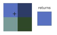
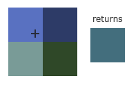
The difference shows when a small texture is stretched over a large area, so that each texel covers many pixels on screen. Point filtering then shows the texels as hard-edged blocks, the look of old pixel-art games. Linear filtering gives a smooth, slightly blurry image without visible blocks, which is what we want most of the time.
The filter can be chosen separately for
Mipmaps
Picture a long floor covered in one tiled texture. Near the camera, a texel covers a few screen pixels. Far away, a single screen pixel covers dozens of texels. Sampling just one or four of those texels picks an essentially random colour out of the many the pixel covers, and as the camera moves, which texels get picked changes from frame to frame. Distant surfaces shimmer and sparkle. Reading a large texture to draw a few pixels is also slow, because it uses the GPU's memory caches badly.
The fix is to prepare smaller copies of the texture in advance, each half the width and height of the one before, down to a single texel. These are
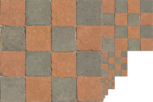
When sampling, the GPU estimates how many texels one screen pixel covers and reads from the level where that is about one. Distant surfaces read small, pre-averaged levels, which is both stable and fast. The whole chain costs only a third more memory than the full-size image. The level with the full image is level 0; a 512 by 512 texture, like the crate in this lesson, has ten levels, ending at 1 by 1.
The sampler then has one more choice to make: whether to use the single nearest level (point) or to blend between the two nearest levels (linear), which hides the visible seam where one level gives way to the next. That is the MIP part of the filter names. D3D11_FILTER_MIN_MAG_MIP_LINEAR, linear within each level and between levels, is often called
Our sampler
The lesson creates one sampler at startup and binds it:
; A sampler: how textures are filtered and what happens past their edges. Anisotropic
; filtering stays sharp on surfaces seen at a slant; wrap repeats the image.
invoke create_sampler, D3D11_FILTER_ANISOTROPIC, D3D11_TEXTURE_ADDRESS_WRAP
mov sampler, rax
vcall context, ID3D11DeviceContext_PSSetSamplers, 0, 1, ADDR sampler
learn/gpu.asm, since every later lesson needs a sampler or two. It takes the filter and one address mode for all three axes:
; rcx: filter, rdx: address mode -> rax: ID3D11SamplerState
;
; How textures are filtered, and what happens past their edges.
align 16
create_sampler proc filter:qword, address:qword
    local desc:D3D11_SAMPLER_DESC, sampler:qword
    invoke mem_zero, ADDR desc, sizeof D3D11_SAMPLER_DESC
    mov eax, dword ptr filter
    mov desc.Filter, eax
    mov eax, dword ptr address
    mov desc.AddressU, eax
    mov desc.AddressV, eax
    mov desc.AddressW, eax
    mov desc.MaxAnisotropy, 8
    mov desc.ComparisonFunc, D3D11_COMPARISON_NEVER
    mov dword ptr desc.MaxLOD, 7F7FFFFFh    ; D3D11_FLOAT32_MAX
    vcall device, ID3D11Device_CreateSamplerState, ADDR desc, ADDR sampler
    AssertHr
    mov rax, sampler
    ret
create_sampler endp
The filter is a step beyond trilinear.
MaxLOD is the highest mip level the sampler may use (LOD, level of detail, is another name for the mip level). Setting it to the largest float means "no limit". That float is written by its bits, 7F7FFFFFh: the largest exponent below infinity and every mantissa bit set. Storing a 32-bit integer into a float field is fine in assembly, which only sees four bytes either way, and it saves putting the constant in memory. ComparisonFunc only matters for the comparison samplers of Shadow Mapping; it is set to a valid value here so the description holds no zero that means nothing.
Samplers are bound to
Loading and creating textures
Before we can use an image we have to get its pixels out of a file. Image formats are complicated, each in its own way: PNG compresses losslessly, JPEG approximates the image with frequency components, and both have many variants. Writing a loader for even one of them is a project. LearnOpenGL uses stb_image.h, a popular single-file C library. We don't need a library at all: Windows comes with the includes/image.asm wraps it in one procedure.
image.asm
WIC is a COM API like Direct3D. Its starting point is an imaging factory, created once:
align 16
image_init proc
    cmp image_wic, 0
    jne done
    cmp arena.base, 0
    jne have_arena
        invoke arenaInit, ADDR arena
    have_arena:
    invoke CoInitializeEx, 0, COINIT_MULTITHREADED
    invoke CoCreateInstance, ADDR CLSID_WICImagingFactory, 0, CLSCTX_INPROC_SERVER, ADDR IID_IWICImagingFactory, ADDR image_wic
    AssertHr
    done:
    ret
image_init endp
saha.asm that file contents and images are taken from.
vcall image_wic, IWICImagingFactory_CreateFormatConverter, ADDR converter
; Whatever the file holds, convert it to 8-bit RGBA. The sixth argument is a double, 0.0.
vcall converter, IWICFormatConverter_Initialize, wic_frame, ADDR GUID_WICPixelFormat32bppRGBA, \
                 WICBitmapDitherTypeNone, 0, 0, WICBitmapPaletteTypeCustom
vcall converter, IWICFormatConverter_GetSize, ADDR w, ADDR h
mov eax, w
mul h
shl rax, 2
mov byte_count, rax
invoke arenaPush, ADDR arena, byte_count, 16
mov rbx, out_ref
mov [rbx].image.pixels, rax
mov eax, w
mov [rbx].image._width, eax
mov eax, h
mov [rbx].image.height, eax
mov eax, w
shl eax, 2
vcall converter, IWICFormatConverter_CopyPixels, 0, rax, byte_count, qword ptr [rbx].image.pixels
One argument deserves a look first. The sixth argument of double, the alpha threshold. A float argument goes in the xmm register of its position, but only the first four positions have registers; from the fifth on, every argument, float or not, is eight bytes on the stack. And 0.0 is all zero bits, so a plain 0 passes it.
The mul h multiplies eax by h into edx:eax, and shl rax, 2 multiplies by four. The result goes into a small structure that the caller passes by address:
image struct
    pixels qword ?      ; RGBA8, width * height * 4 bytes (image_load_hdr: 4 floats a pixel)
    _width dword ?
    height dword ?
image ends
Always converting to four channels spares us a detail LearnOpenGL has to handle: telling GL_RGB images from GL_RGBA ones. Direct3D has no 8-bit three-channel texture format anyway, so even a JPEG with no alpha becomes RGBA, with alpha 255.
Generating a texture
With the pixels in memory, learn/gpu.asm, where every later lesson finds it.
; rcx: path, rdx: 1 for colour data -> rax: ID3D11ShaderResourceView
; ...
align 16
load_texture proc path:qword, srgb:qword
    local img:image, desc:D3D11_TEXTURE2D_DESC, texture:qword, srv:qword, pitch:qword
    invoke image_load, ADDR img, path
    test rax, rax
    jnz loaded
        print "Texture failed to load at path: %s\n", path
        invoke ExitProcess, 1
    loaded:
    invoke mem_zero, ADDR desc, sizeof D3D11_TEXTURE2D_DESC
    mov eax, img._width
    mov desc._Width, eax
    mov eax, img.height
    mov desc.Height, eax
    mov desc.MipLevels, 0                   ; the whole chain
    mov desc.ArraySize, 1
    mov desc.Format, DXGI_FORMAT_R8G8B8A8_UNORM
    cmp srgb, 0
    je linear
        mov desc.Format, DXGI_FORMAT_R8G8B8A8_UNORM_SRGB
    linear:
    mov desc.SampleDesc.Count, 1
    ; Generating mips draws into the texture, so it is a render target too.
    mov desc.BindFlags, D3D11_BIND_SHADER_RESOURCE or D3D11_BIND_RENDER_TARGET
    mov desc.MiscFlags, D3D11_RESOURCE_MISC_GENERATE_MIPS
    vcall device, ID3D11Device_CreateTexture2D, ADDR desc, 0, ADDR texture
    AssertHr
    vcall device, ID3D11Device_CreateShaderResourceView, texture, 0, ADDR srv
    mov eax, img._width
    shl eax, 2
    mov pitch, rax
    vcall context, ID3D11DeviceContext_UpdateSubresource, texture, 0, 0, img.pixels, pitch, 0
    vcall context, ID3D11DeviceContext_GenerateMips, srv
    release texture                         ; the view keeps it alive
    mov rax, srv
    ret
load_texture endp
This is the longest description so far, so let's take it field by field.
- Width and Height are the image's size in texels.
- MipLevels is the number of mip levels. Zero is special: it means the whole chain, down to 1 by 1, however many levels that takes for this size.
- ArraySize is 1, a single image. Textures can also be arrays of images, which is how cubemaps are stored in a later chapter.
- Format is R8G8B8A8_UNORM, matching the bytes WIC gave us. The
srgbargument, when it is not 0, replaces it with an sRGB format; it matters for colour accuracy, and Gamma Correction explains it. This lesson passes 0 for both its textures. - SampleDesc.Count is 1: an ordinary texture, not multisampled.
- BindFlags say how the texture will be used. It will be read by shaders, so D3D11_BIND_SHADER_RESOURCE. It is also marked as a render target, because of the next field.
- MiscFlags asks for D3D11_RESOURCE_MISC_GENERATE_MIPS, permission to have the GPU compute the mipmaps for us. The GPU does that by drawing each level from the one above it, so the texture must be usable as a render target too.
The Usage field is left at zero, which is D3D11_USAGE_DEFAULT: memory the GPU reads and writes, which the CPU can only update through the context. With the description complete, four calls finish the job:
CreateTexture2D creates the texture. We pass no initial data, the0: initial data has to cover every mip level, and we only have level 0.CreateShaderResourceView creates the view a shader reads the texture through. With no view description it covers the whole texture, all its levels.UpdateSubresource copies our pixels intosubresource 0, which for this texture is mip level 0. The0after the subresource is the box to update, and none means the whole level; after the pixels comes therow pitch , the number of bytes from the start of one row to the next: four bytes per texel, times the width, worked out with a shift by two.GenerateMips fills in every other level from level 0, the counterpart ofglGenerateMipmap . It takes the shader resource view, and generates all the levels the view covers.
The procedure returns the view. That is all the rest of the program needs: shaders read textures through views, never through the texture object itself. So the procedure's own pointer to the texture is released: the view holds a reference of its own, which keeps the texture alive as long as the view is.
The lesson loads two textures this way, a wooden crate and a smiling face, both from resources/textures:
invoke filesystem_path, "resources/textures/container.jpg"
invoke load_texture, rax, 0
mov textures[0], rax
invoke filesystem_path, "resources/textures/awesomeface.png"
invoke load_texture, rax, 0
mov textures[8], rax
textures is an array of two pointers in the data section, textures qword 2 dup(0). MASM's index in brackets counts bytes, not elements, so the second pointer is textures[8].
Applying textures
The vertices have a texture coordinate now, so the input layout describes it, right after the position:
semantic_position byte "POSITION", 0
semantic_texcoord byte "TEXCOORD", 0
align 8
vertex_layout D3D11_INPUT_ELEMENT_DESC <offset semantic_position, 0, DXGI_FORMAT_R32G32B32_FLOAT, 0, 0, D3D11_INPUT_PER_VERTEX_DATA, 0>
              D3D11_INPUT_ELEMENT_DESC <offset semantic_texcoord, 0, DXGI_FORMAT_R32G32_FLOAT, 0, 12, D3D11_INPUT_PER_VERTEX_DATA, 0>
DXGI_FORMAT_R32G32_FLOAT is two floats, \(u\) and \(v\), starting 12 bytes into the vertex. A vertex is five floats, so the stride we bind the vertex buffer with is 20 bytes, stride dword 20. The rectangle is drawn with the same index buffer as in Hello Triangle, two triangles from four vertices.
The vertex shader passes the coordinate through to the pixel shader, so that it is interpolated across the rectangle:
struct vs_out
{
    float4 position : SV_Position;
    float2 uv : TEXCOORD;
};

vs_out vs_main(float3 position : POSITION, float2 uv : TEXCOORD)
{
    vs_out o;
    o.position = float4(position, 1.0);
    o.uv = uv;
    return o;
}
The inputs are plain parameters this time, each with its semantic, rather than a struct: HLSL accepts either. The pixel shader needs the textures and the sampler, and they are declared at the top of the file:
Texture2D crate : register(t0);
Texture2D face : register(t1);
SamplerState linear_wrap : register(s0);
A Texture2D is a 2D texture the shader reads, through a view bound to a texture slot: register(t0) is slot 0, t1 slot 1. A SamplerState is a sampler, in sampler slot s0. GLSL combines both into one sampler2D variable; HLSL keeps them apart, matching Direct3D's separate objects. Sampling then takes both, in method-call form:
float4 ps_main(vs_out p) : SV_Target
{
    return lerp(crate.Sample(linear_wrap, p.uv), face.Sample(linear_wrap, p.uv), 0.2);
}
crate.Sample(linear_wrap, p.uv) reads the crate texture at the pixel's interpolated coordinate, filtered and addressed as the sampler says, and returns a float4 colour. GLSL writes texture(sampler, uv). The face is sampled the same way, with the same sampler, and the two are blended with lerp(a, b, t) is \(a + (b - a)\,t\), so with \(t = 0.2\) we get 80% crate and 20% face.
Texture units
OpenGL has sampler2D uniform which unit to read with register(t0) and register(t1), so there is nothing to tell it from the program. All that remains is to bind the two views to those slots, which one call does, since slots are consecutive:
; the two textures, in registers t0 and t1
vcall context, ID3D11DeviceContext_PSSetShaderResources, 0, 2, ADDR textures
Starting at slot 0, bind two views from the array: the crate to t0 and the face to t1. Each stage has 128 texture slots and 16 sampler slots, which is more than enough. Then the usual drawing calls follow, and this is the result:
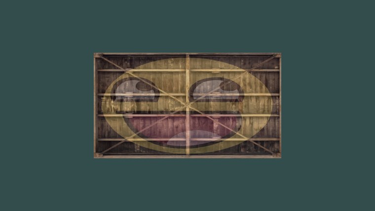
One happy crate, the right way up, without flipping anything. The image looks stretched sideways because the rectangle spans half the window in each direction, and the window is wider than it is tall. That gets fixed when we add a projection matrix in Coordinate Systems.
The full program is here, its shaders here, the image loader here, and
Additional resources
- D3D11_SAMPLER_DESC: every sampler setting, with its default.
- D3D11_FILTER: the full list of filter combinations.
- Subresources: how mip levels and array slices are numbered.
- About the Windows Imaging Component: the decoders behind
image.asm. - LearnOpenGL's Textures: the same chapter in OpenGL.
Exercises
- Change only the pixel shader so that the face looks the other way, while the crate stays as it is.
- Change the texture coordinates to run from 0 to 2 instead of 0 to 1, so the face appears four times. Then try each address mode on the sampler. Finally, make the crate clamp while the face still repeats: you'll need a second sampler from
create_sampler , with D3D11_TEXTURE_ADDRESS_CLAMP, bound to slots1and used for one of the two textures. - Choose texture coordinates that show only a small area in the middle of the textures, so that each texel covers many pixels. Set the filter to D3D11_FILTER_MIN_MAG_MIP_POINT and compare it with linear filtering.
- Put the 0.2 blend amount in a constant buffer, as in the Shaders chapter, and change it with the up and down arrow keys while they are held (
invoke key_down, VK_UPand VK_DOWN, fromlearn/window.asm).