Coordinate Systems
In the last chapter a matrix moved our squares around, but the numbers we fed it were still screen numbers: 0.5 meant "a quarter of the window from the centre". That is how the pipeline wants positions at the end of the vertex shader. After the division by w, which we have not met properly yet, every visible vertex must lie in
The chain passes through several
Local space , also called object spaceWorld space View space , also called eye space or camera spaceClip space Screen space
This chapter walks a vertex through all of them, and by the end we are drawing real 3D cubes in perspective.
The global picture
Three matrices do most of the work: the
The green spaces are ours: we choose them and write the matrices between them. The grey ones are fixed by Direct3D.
- A model's vertices start out in
local coordinates , relative to the model's own origin. - The model matrix places the model in the scene, giving
world coordinates , relative to one origin shared by everything. - The view matrix re-expresses the world as seen from the camera:
view coordinates . - The projection matrix turns view coordinates into
clip coordinates , which decide what is visible, and is where perspective comes from. This is what the vertex shader returns asSV_Position. - The rasterizer divides by w to get NDC, and the
viewport transform turns NDC into pixel positions on the render target.
Why so many steps, when the three matrices could be multiplied into one? Because each space is the natural place for some kind of work. Editing a model is easiest in local space, placing things relative to each other is easiest in world space, and lighting, as we will see, can be done in world or view space depending on what it needs. Keeping the matrices separate keeps all of those spaces within reach.
Local space
Local space is where an object's vertices are written down. Someone building a crate in a modelling program puts its centre at the origin and its corners half a unit away, without knowing or caring where it will end up in a game. Every model starts like that. Our cube is the same: the 36 vertices of cube_vertices run from -0.5 to 0.5 on every axis, around (0, 0, 0). Those are local coordinates.
World space
If we drew every model straight from its local coordinates, they would all pile up at the origin. T * R * S order of the last chapter) that turns the object's local coordinates into world coordinates. Think of a house modelled too big and facing the wrong way: its model matrix scales it down, turns it to face the street, and moves it onto its plot. The matrices that moved our squares in the last chapter were model matrices in all but name.
View space
Clip space
At the end of the vertex shader the pipeline expects coordinates in
The region a projection matrix keeps is called the
Precisely, a clip-space position \((x, y, z, w)\) is visible when
\[-w \le x \le w, \qquad -w \le y \le w, \qquad 0 \le z \le w\]
The last condition is where Direct3D and OpenGL part ways: OpenGL keeps \(-w \le z \le w\). Direct3D's z is clipped against the near and far planes only while DepthClipEnable is set in the rasterizer state, as it is in all our lessons. After clipping, the rasterizer performs the
with x and y now in -1..1 and z in 0..1. This happens automatically after every vertex shader. Then the viewport takes over.
A projection matrix comes in one of two forms, each with its own shape of frustum:
Orthographic projection
An
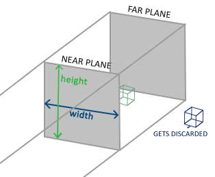
It leaves w at 1, so the division by w changes nothing. math.asm builds one with
; rcx: out, xmm1: left, xmm2: right, xmm3: bottom, [rsp+32]: top, [rsp+40]: z_near, [rsp+48]: z_far
;
; Right-handed orthographic projection onto 0..1 depth.
align 16
m4_ortho proc out_ref:qword, left_:qword, right_:qword, bottom:qword, top:qword, z_near:qword, z_far:qword
    movss real4 ptr left_, xmm1
    movss real4 ptr right_, xmm2
    movss real4 ptr bottom, xmm3
    call m4_identity
    ; 2 / (right - left), -(right + left) / (right - left)
    movss xmm0, real4 ptr right_
    subss xmm0, real4 ptr left_
    movf xmm1, 2.0
    divss xmm1, xmm0
    movss real4 ptr [rcx + 0], xmm1
    movss xmm1, real4 ptr right_
    addss xmm1, real4 ptr left_
    divss xmm1, xmm0
    xorps xmm1, math_sign_mask
    movss real4 ptr [rcx + 12], xmm1
    ; ...
    ; 1 / (near - far), near / (near - far)
    movss xmm0, real4 ptr z_near
    subss xmm0, real4 ptr z_far
    movss xmm1, math_one
    divss xmm1, xmm0
    movss real4 ptr [rcx + 40], xmm1
    movss xmm1, real4 ptr z_near
    divss xmm1, xmm0
    movss real4 ptr [rcx + 44], xmm1
    ret
m4_ortho endp
The first four arguments after out give the box's sides in view space, and the last two are the distances to the near and far planes, both positive, in front of the camera. Six floats are more than the registers hold: by the Win64 rule, each argument takes the register of its position, so left, right and bottom, the second to fourth arguments, arrive in xmm1, xmm2 and xmm3, and from the fifth on they are on the stack, which the procedure sees as its named arguments top, z_near and z_far. The three that came in registers are stored into their own stack slots first, where the prologue had put whatever rdx, r8 and r9 held, so all six can be read the same way. Negating is xorps with math_sign_mask, which flips the sign bit. Rows 0 and 1 scale and shift x and y so that left..right and bottom..top become -1..1. Row 2 is Direct3D's version: a point on the near plane, at \(z = -n\), comes out at depth 0, and one on the far plane, at \(z = -f\), at depth 1. GLM's glm::ortho maps the same planes to -1 and 1 instead.
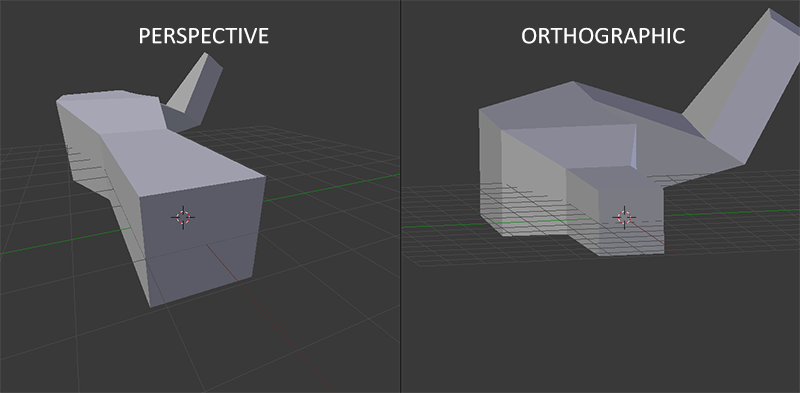
Because size does not change with distance, orthographic projection looks flat. That is exactly what we want for 2D interfaces, technical drawings and, in later chapters, the shadow maps of a directional light, but it does not look like the world we see.
Perspective projection
Stand between two railway tracks and look along them: they seem to meet in the distance, and the sleepers grow smaller the further away they are. That is
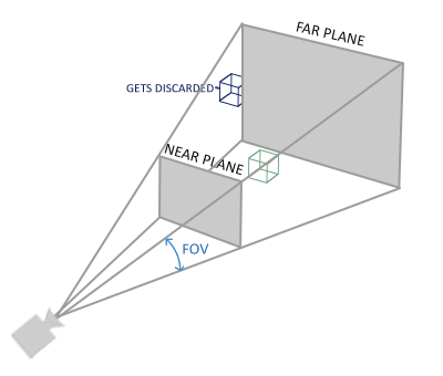
The trick is in w. A perspective matrix copies the point's distance in front of the camera into w. The division by w then shrinks x and y in proportion to distance: a point twice as far away ends up twice as close to the centre of the screen. Our version is
; rcx: out, xmm1: fovy in radians, xmm2: aspect, xmm3: z_near, [rsp+32]: z_far
;
; Right-handed perspective onto D3D's 0..1 depth range.
align 16
m4_perspective proc out_ref:qword, fovy:qword, aspect:qword, z_near:qword, z_far:qword
    movss real4 ptr aspect, xmm2
    movss real4 ptr z_near, xmm3
    movaps xmm0, xmm1
    mulss xmm0, math_half
    call tanf
    movss xmm1, math_one
    divss xmm1, xmm0            ; f = 1 / tan(fovy / 2)

    mov rcx, out_ref
    xorps xmm0, xmm0
    movups [rcx], xmm0
    movups [rcx + 16], xmm0
    movups [rcx + 32], xmm0
    movups [rcx + 48], xmm0
    movss xmm0, xmm1
    divss xmm0, real4 ptr aspect
    movss real4 ptr [rcx + 0], xmm0         ; f / aspect
    movss real4 ptr [rcx + 20], xmm1        ; f
    movss xmm2, real4 ptr z_near
    subss xmm2, real4 ptr z_far             ; near - far
    movss xmm0, real4 ptr z_far
    divss xmm0, xmm2
    movss real4 ptr [rcx + 40], xmm0        ; far / (near - far)
    movss xmm0, real4 ptr z_near
    mulss xmm0, real4 ptr z_far
    divss xmm0, xmm2
    movss real4 ptr [rcx + 44], xmm0        ; near * far / (near - far)
    mov dword ptr [rcx + 56], 0BF800000h    ; -1
    ret
m4_perspective endp
Elements 0, 5, 10, 11 and 14 are at byte offsets 0, 20, 40, 44 and 56; the -1 is written by its bits, 0BF800000h. The tangent comes from math.asm's fptan instruction. Besides out, it takes four parameters, the same four as glm::perspective:
- fovy, the
field of view : the angle between the top and bottom of the frustum, in radians. 45 degrees looks natural; much wider gives the stretched look of a fish-eye lens. - aspect, the
aspect ratio : the viewport's width divided by its height. The frustum is made that much wider than it is tall, which does properly what our aspect scale did by hand in the last chapter. - z_near and z_far, the distances to the near and far planes. 0.1 and 100 are typical. Set the near plane too far out, say at 10, and everything closer than that is clipped, the familiar effect of walking into a wall in a game and seeing through it.
Four floats after an address: fovy, aspect and z_near are the second, third and fourth arguments, so they travel in xmm1, xmm2 and xmm3, and z_far, the fifth, goes on the stack, at [rsp+32], just above the 32 bytes of shadow space that every call reserves for the first four. We will see the call below.
Written as a matrix, with \(c = 1 / \tan(\text{fovy} / 2)\) (the code's f), \(a\) the aspect, and \(n\) and \(f\) the near and far distances:
\[P_{D3D} = \begin{bmatrix} \frac{c}{a} & 0 & 0 & 0 \\ 0 & c & 0 & 0 \\ 0 & 0 & \frac{f}{n - f} & \frac{n f}{n - f} \\ 0 & 0 & -1 & 0 \end{bmatrix} \qquad P_{GL} = \begin{bmatrix} \frac{c}{a} & 0 & 0 & 0 \\ 0 & c & 0 & 0 \\ 0 & 0 & \frac{f + n}{n - f} & \frac{2 n f}{n - f} \\ 0 & 0 & -1 & 0 \end{bmatrix}\]The bottom row is what puts the distance into w: \(w = -z\), positive for anything in front of a camera that looks down -z. The first two rows are identical in both APIs. Only the two entries that make depth differ, and for good reason. Check ours at the near plane, \(z = -n\):
\[z_{clip} = \frac{f}{n - f}(-n) + \frac{n f}{n - f} = 0, \qquad w = n, \qquad z_{ndc} = 0\]and at the far plane, \(z = -f\):
\[z_{clip} = \frac{-f^2 + n f}{n - f} = f, \qquad w = f, \qquad z_{ndc} = 1\]
So the near plane maps to depth 0 and the far plane to 1, which is Direct3D's range. The GL matrix sends them to -1 and 1. Used unchanged with Direct3D, everything that came out below 0, which with a distant far plane is everything nearer than about twice the near distance, would be clipped, and half of the depth buffer's range would go unused. That is the one change projection needs, and it is why math.asm carries its own.
Side by side, the two projections look like this in Blender, perspective on the left and orthographic on the right. In the orthographic view the far end of the scene is drawn as large as the near end:
Putting it all together
One matrix per step, and a vertex goes from local space to clip space as
\[V_{clip} = M_{projection} \cdot M_{view} \cdot M_{model} \cdot V_{local}\]
read, as always, from right to left: model first, projection last. The vertex shader computes this and returns it as SV_Position; the rasterizer clips, divides by w, and applies the viewport.
The viewport transform
The
cvtsi2ss xmm0, scr_width
movss viewport._Width, xmm0
cvtsi2ss xmm0, scr_height
movss viewport.Height, xmm0
storef viewport.MaxDepth, 1.0
and the rasterizer computes pixel coordinates from NDC like this:
\[X = (x_{ndc} + 1) \cdot \tfrac{\text{Width}}{2} + \text{TopLeftX}, \qquad Y = (1 - y_{ndc}) \cdot \tfrac{\text{Height}}{2} + \text{TopLeftY}, \qquad Z = \text{MinDepth} + z_{ndc} \cdot (\text{MaxDepth} - \text{MinDepth})\]Note the \(1 - y_{ndc}\). Direct3D's screen space starts at the top-left corner of the render target and its y grows downwards, like the rows of an image. NDC's y still points up, so the viewport flips it. OpenGL's window coordinates start at the bottom-left instead, which is one reason images and textures come out upside down when code moves between the two APIs. The last part maps depth onto MinDepth..MaxDepth, 0..1 here, which is what ends up in the depth buffer.
Going 3D
Time to use all of this. We need a model matrix, a view matrix and a projection matrix, and a shader that applies them. The shader first: the three matrices go into one constant buffer,
cbuffer object : register(b0)
{
    float4x4 model;
    float4x4 view;
    float4x4 projection;
};
mirrored on the CPU by a structure with the same three fields in the same order:
; Mirrors `cbuffer object` in the shader.
object_constants struct
    model mat4 <>
    view mat4 <>
    projection mat4 <>
object_constants ends
and the vertex shader applies them, right to left, in nested
vs_out vs_main(vs_in v)
{
    vs_out o;
    o.position = mul(projection, mul(view, mul(model, float4(v.position, 1.0))));
    o.uv = v.uv;
    return o;
}
The shader file starts with #pragma pack_matrix(row_major), as every shader that reads our matrices does. Each float4x4 takes exactly four registers, so the buffer is 192 bytes with no padding to worry about.
Now the matrices. For the view matrix, remember that the camera always sits at the origin of view space. To see a model that sits at the world origin we have to step back from it, and stepping the camera back is the same thing as pushing the whole world away. Our world is right-handed: +x to the right, +y up and +z coming out of the screen towards us.
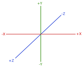
So "backwards" for the camera is +z, and the view matrix moves the world the opposite way, three units along -z, with view_offset vec3 <0.0, 0.0, -3.0> in the data section:
; view = translate(0, 0, -3): the world moves away from the eye
invoke m4_translate, ADDR c.view, ADDR view_offset
; projection = perspective(45 degrees, width / height, 0.1, 100)
movf xmm0, 100.0
movss real4 ptr [rsp + 32], xmm0        ; z_far, the fifth argument, on the stack
movf xmm0, 45.0
call radians
movaps xmm1, xmm0                       ; fovy
cvtsi2ss xmm2, scr_width
cvtsi2ss xmm0, scr_height
divss xmm2, xmm0                        ; aspect
movf xmm3, 0.1                          ; z_near
lea rcx, c.projection
call m4_perspective
and the projection is a 45 degree perspective with the window's aspect ratio, from 0.1 to 100 units. The view matrix lands straight in the constant buffer's mirror, c, and so does the projection. Both are rebuilt every frame, as in LearnOpenGL, though neither changes.
[rsp + 32], the slot above the four shadow-space slots: the MASM64 SDK's prologue has already made room in rsp stays put and the slot is simply written. The other floats go in xmm1 to xmm3 by position, and rcx, the first argument, gets the address of the result. The order of the steps matters: xmm0, so the fovy is converted before anything else is loaded, and the aspect, which needs xmm0 as scratch, is worked out before z_near goes into xmm3. rsp.
Before cubes, it is worth trying the smallest possible step. If the model matrix tilts the square from the last chapter back by 55 degrees about the x axis,
model = rotate(radians(-55), (1, 0, 0))the square looks as if it lies on a floor in front of us: tilted away, three units off, and narrowing towards its far edge. That is perspective doing its job. Our lesson goes straight on to cubes.
More 3D
A cube has six faces of two triangles each, so drawn without an index buffer it is 36 vertices. Ours carry a normal as well as a position and a texture coordinate, eight floats or 32 bytes each. The normals are for the lighting chapters; this lesson's shader reads them in vs_in but does not use them. The cube is in learn/cube.asm, since most later lessons draw it too. One face, and the layout, look like this:
cube_vertices label byte
              ; right (+x)
              real4   0.5,  -0.5,   0.5,     1.0,   0.0,   0.0,   0.0, 1.0
              real4   0.5,  -0.5,  -0.5,     1.0,   0.0,   0.0,   1.0, 1.0
              real4   0.5,   0.5,  -0.5,     1.0,   0.0,   0.0,   1.0, 0.0
              real4   0.5,  -0.5,   0.5,     1.0,   0.0,   0.0,   0.0, 1.0
              real4   0.5,   0.5,  -0.5,     1.0,   0.0,   0.0,   1.0, 0.0
              real4   0.5,   0.5,   0.5,     1.0,   0.0,   0.0,   0.0, 0.0
              ; ...
cube_stride equ 32
cube_vertices_size equ 36 * cube_stride
.erre ($ - cube_vertices) eq cube_vertices_size

cube_semantic_position byte "POSITION", 0
cube_semantic_normal byte "NORMAL", 0
cube_semantic_texcoord byte "TEXCOORD", 0
align 8
cube_layout D3D11_INPUT_ELEMENT_DESC <offset cube_semantic_position, 0, DXGI_FORMAT_R32G32B32_FLOAT, 0, 0, D3D11_INPUT_PER_VERTEX_DATA, 0>
            D3D11_INPUT_ELEMENT_DESC <offset cube_semantic_normal, 0, DXGI_FORMAT_R32G32B32_FLOAT, 0, 12, D3D11_INPUT_PER_VERTEX_DATA, 0>
            D3D11_INPUT_ELEMENT_DESC <offset cube_semantic_texcoord, 0, DXGI_FORMAT_R32G32_FLOAT, 0, 24, D3D11_INPUT_PER_VERTEX_DATA, 0>
cube_layout_count equ 3
.erre is an assembly-time check: if the bytes from cube_vertices to here are not exactly 36 vertices of 32 bytes, the assembly stops with an error, so a row left out or added can't go unnoticed.
The texture coordinates have v growing downwards, Direct3D's way, so each face shows the crate the right way up. The cube is drawn with a plain
vcall context, ID3D11DeviceContext_IASetVertexBuffers, 0, 1, ADDR cube_vb, ADDR stride, ADDR offset_
; ...
vcall context, ID3D11DeviceContext_Draw, 36, 0
If you draw a spinning cube with only what we have so far, it looks wrong. Faces at the back show through faces at the front, and the cube seems to turn inside out as it rotates. The reason is that the output merger writes every pixel the pixel shader produces, in the order the triangles arrive. A back face listed after a front face simply paints over it. We need a way to keep the nearest surface at each pixel.
Z-buffer
That way is the
GLFW creates a depth buffer along with LearnOpenGL's window. Here we create it ourselves, like everything else: a texture with a depth format, and a learn/window.asm, and the lesson asks for it right after the window with call window_create_depth:
; A depth buffer the size of the window: 24 bits of depth, 8 of stencil.
align 16
window_create_depth proc
    local desc:D3D11_TEXTURE2D_DESC
    invoke mem_zero, ADDR desc, sizeof D3D11_TEXTURE2D_DESC
    mov eax, scr_width
    mov desc._Width, eax
    mov eax, scr_height
    mov desc.Height, eax
    mov desc.MipLevels, 1
    mov desc.ArraySize, 1
    mov desc.Format, DXGI_FORMAT_D24_UNORM_S8_UINT
    mov desc.SampleDesc.Count, 1
    mov desc.BindFlags, D3D11_BIND_DEPTH_STENCIL
    vcall device, ID3D11Device_CreateTexture2D, ADDR desc, 0, ADDR depth_texture
    vcall device, ID3D11Device_CreateDepthStencilView, depth_texture, 0, ADDR depth_dsv
    ret
window_create_depth endp
DXGI_FORMAT_D24_UNORM_S8_UINT packs 24 bits of depth and 8 bits of stencil into each pixel; the stencil part waits for Stencil testing. The bind flag D3D11_BIND_DEPTH_STENCIL says the texture will be used as a depth buffer, the role a render target view plays for colour.
Every frame we bind it next to the back buffer, and clear it along with the colour:
vcall context, ID3D11DeviceContext_OMSetRenderTargets, 1, ADDR backbuffer_rtv, depth_dsv
vcall context, ID3D11DeviceContext_RSSetViewports, 1, ADDR viewport
vcall context, ID3D11DeviceContext_ClearRenderTargetView, backbuffer_rtv, floats(0.2, 0.3, 0.3, 1.0)
; The depth to clear to is a float: the fourth argument, counting `this`, so it travels in
; xmm3, and the 0 in its place on the vcall line is only a placeholder.
movf xmm3, 1.0
vcall context, ID3D11DeviceContext_ClearDepthStencilView, depth_dsv, D3D11_CLEAR_DEPTH or D3D11_CLEAR_STENCIL, 0, 0
The clear shows the other way of passing a float to a call: load its xmm register with macros.asm that puts the constant in the data section and movsses it, and write any placeholder in its place in the argument list. r9, which the method ignores, since its fourth argument is a float and is read from xmm3. xmm register on the way, so the value survives until the call. Depth is cleared to 1.0, the far plane, so the first thing drawn at any pixel is always nearer and passes. Without the clear, last frame's depths would still be there, and this frame's cubes would be tested against where the cubes were a moment ago.
In OpenGL the depth test is off until glEnable(GL_DEPTH_TEST). In Direct3D it is part of the 0 there, as the earlier lessons did, is what turns it off. Depth testing creates depth-stencil states of its own to change the comparison.
More cubes!
One cube is a start. The scene in this lesson has ten, all identical, at different places in the world. Since they share their shape, they share one vertex buffer and one input layout; the only thing that differs between them is the model matrix. Here is where they go, in world space:
; world space positions of our cubes
align 4
cube_positions vec3 <0.0, 0.0, 0.0>
               vec3 <2.0, 5.0, -15.0>
               vec3 <-1.5, -2.2, -2.5>
               ; ...
               vec3 <-1.3, 1.0, -1.5>
cube_rotation_axis vec3 <1.0, 0.3, 0.5>
and the loop that draws them, inside the render loop, after the view and projection have been set:
xor ebx, ebx
cubes:
    ; angle = radians(20 * i), and every third cube spins with time
    cvtsi2ss xmm0, ebx
    movf xmm1, 20.0
    mulss xmm0, xmm1
    call radians
    mov eax, ebx
    xor edx, edx
    mov ecx, 3
    div ecx
    test edx, edx
    jnz still
        addss xmm0, current_frame
    still:
    ; model = translate(cube_positions[i]) * rotate(angle, (1, 0.3, 0.5))
    movaps xmm1, xmm0
    lea rcx, rotation
    lea r8, cube_rotation_axis
    call m4_rotate
    imul eax, ebx, sizeof vec3
    lea rdx, cube_positions
    add rdx, rax
    invoke m4_translate, ADDR translation, rdx
    invoke m4_mul, ADDR c.model, ADDR translation, ADDR rotation
    invoke update_buffer, constants, ADDR c, sizeof object_constants
    vcall context, ID3D11DeviceContext_Draw, 36, 0
    inc ebx
    cmp ebx, 10
    jb cubes
The counter lives in ebx, one of the registers every call must leave as it found them, so it survives all the calls in the loop's body; USING rbx and SaveRegs. "Every third" is the remainder of a division: div ecx divides edx:eax by 3, leaving the remainder in edx. And cube_positions[i] is reached by computing its address, i * 12 bytes past the start, in a register. A global indexed by a register directly, like cube_positions[rbx * 12], would need an absolute 32-bit address, which a 64-bit program can't use; lea gets the address relative to the instruction first.
Each cube is rotated about the same tilted axis, (1, 0.3, 0.5), by 20 degrees more than the one before, and then moved to its position: \(T \cdot R\) again, so it turns about its own centre. Every third cube, the first included, also adds the time to its angle and keeps turning. LearnOpenGL leaves that as an exercise; our lesson does it. The view and projection stay the same for all ten, but the whole constant buffer, all three matrices, is written again before each draw, since D3D11_MAP_WRITE_DISCARD gives us a fresh buffer every time and does not keep the previous contents.
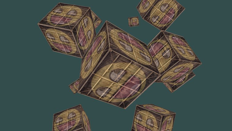
Ten crates, near ones large and far ones small, each hiding what is behind it. The one at the origin fills the middle of the view, three units in front of the camera. The full program is here, the cube here, and its shaders here.
Additional resources
- OpenGL Projection Matrix: Song Ho Ahn's derivation of both projections, step by step. It derives the GL depth range; replace "-1" with "0" at the near plane and the same steps give ours.
- Getting started with the rasterizer stage: Microsoft on viewports and the viewport transform.
- Configuring depth-stencil functionality: depth buffers, views and depth-stencil states in Direct3D 11.
- LearnOpenGL's Coordinate Systems: the OpenGL version of this chapter.
Exercises
- Change the field of view and the aspect ratio passed to
m4_perspective . Try 90 and 20 degrees, and an aspect of 1. Explain each result in terms of the frustum. - Move the camera by changing the view matrix: translate the world along x and y as well as z, and add a rotation. Remember that the view matrix moves the world, not the camera.
- Pass
0instead of depth_dsv toOMSetRenderTargets and watch the cubes break up. Then put it back and stop clearing the depth buffer instead. Why does that go wrong differently? - Replace the perspective projection with
m4_ortho , keeping the window's aspect ratio (for example left -4, right 4, bottom -2.25, top 2.25, near 0.1 and far 100: three floats inxmm1toxmm3and three on the stack at[rsp+32],[rsp+40]and[rsp+48]). Which cubes can you no longer tell apart by distance?